
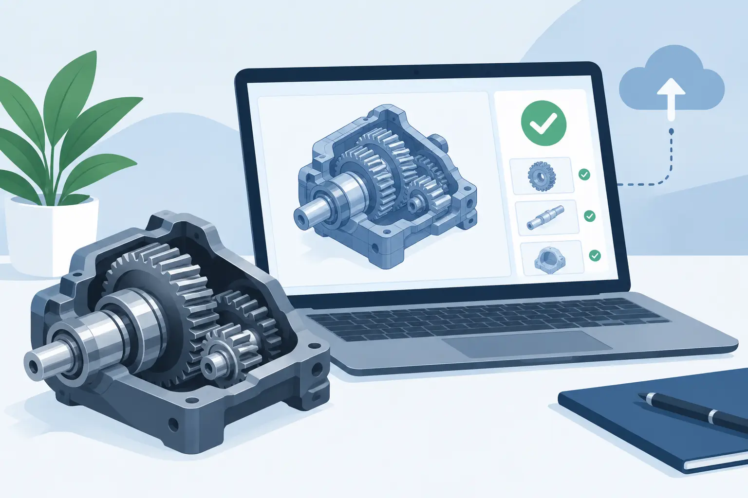
A gear pair can show the correct ratio and still fail as an assembly. The teeth may mesh in isolation, yet the pinion may collide with a housing wall, the shaft may not provide a bearing seat, or a chosen centre distance may leave no credible mounting arrangement. To validate gear assemblies online properly, assess the mechanism as connected production geometry, not as a collection of calculated values.
That distinction matters most when a concept is moving quickly. A compact gearbox, reducer or rack drive often begins with ratio, torque and available space. By the time individual parts have been modelled in general-purpose CAD, a poor tooth combination or impossible bearing arrangement can be expensive to change. Online validation is useful when it brings those constraints forward, while the dimensions are still parameters rather than reworked solids.
Start with the tooth system, not the ratio alone
A ratio is only one output of a gear design. For involute spur and helical gears, the tooth count, module, pressure angle, helix angle, face width and centre distance together define whether the pair has coherent meshing geometry. Changing one value can alter several conditions at once.
For example, reducing pinion tooth count may help package a drivetrain, but it can introduce undercut or weaken the tooth root. Increasing module increases tooth size and load capacity, but also changes pitch diameters, centre distance and the required housing envelope. A valid online workflow should make these dependencies visible rather than accepting a ratio and drawing two generic cylinders with teeth.
True involute geometry is particularly relevant here. It provides a tooth form that can be inspected, manufactured and assessed against the rest of the mechanism. If the output is only a visual approximation, it cannot reliably support a CAD handoff or a production decision.
Check for interference at the intended centre distance
The centre distance is not a cosmetic setting. It controls the operating relationship between the gears. For a spur pair, it must agree with the selected module and tooth counts. For helical gears, the relationship also depends on the normal or transverse tooth system used by the design.
Validation should flag configurations that cannot assemble correctly, as well as combinations with poor practical margins. This is where a browser-based mechanism tool has an advantage over a disconnected calculator: the calculated values, generated teeth and assembly position can be reviewed together.
Do not treat a green status as a substitute for engineering judgement. A design may be geometrically valid but still unsuitable for its duty cycle, material, lubrication or expected backlash. Validation narrows the field to credible configurations. It does not remove the need to define the application.
Validate the assembly geometry around the gears
A gear is carried by shafts, supported by bearings and retained within a housing. Those interfaces determine whether a theoretically correct mesh can become a real part. The practical question is not simply whether two gears rotate. It is whether they rotate with enough clearance, support and assembly access.
Inspect shaft diameters against bores and hubs first. A small pinion bore may be acceptable for a light mechanism, but it may not leave adequate material around a keyway, set screw or clamping feature. Likewise, a long unsupported shaft can introduce deflection that is absent from a simple geometry check.
Bearing positions deserve the same attention. Bearings need usable seat lengths, sensible spacing and clearance from gear hubs, shoulders and housing features. A compact design can become difficult to assemble when the gear must pass a bearing shoulder, or when there is no route to fit a retaining ring. These are not secondary details. They are assembly geometry.
Housing validation is equally useful. Check radial and axial clearances around rotating solids, confirm that mounting faces remain available, and look for conflicts between fasteners and gears. If a motor interface is part of the design, inspect the motor shaft, pilot feature and fixing pattern in the same view. Decisions stay visible when the full mechanism is present.
Use 3D and exploded views for different questions
A live 3D assembly view is best for checking spatial relationships: gear mesh, rotating clearances, shaft alignment and housing volume. Rotate the mechanism rather than relying on one isometric view. Tight configurations often reveal a collision only from the side or along the shaft axis.
An exploded view answers a different question: can the mechanism be put together in a credible order? It exposes hidden interfaces between gears, bearings, shafts and covers. It also helps identify parts that have no insertion path once neighbouring components are installed.
Neither view replaces a tolerance stack-up or detailed finite element analysis. They do, however, catch the kind of packaging errors that are otherwise found when the first printed prototype or machined housing is already on the bench.
Treat bearing and shaft guidance as design constraints
Bearing-fit guidance should inform early design choices rather than be applied after the gear dimensions are frozen. Bearing bores influence shaft diameter, shaft diameter influences gear bore and hub proportions, and those proportions affect the available face width and housing size.
There is always a trade-off. Larger bearings can improve support and durability, but consume radial space and may force a larger centre distance or enclosure. Smaller bearings can help a compact actuator, yet may reduce stiffness and leave little tolerance for misalignment. The correct choice depends on load direction, speed, duty cycle, environment and the required service life.
For a prototype, a guided bearing selection can provide a sound starting point. For a production mechanism, confirm fits, retention, lubrication, thermal behaviour and supplier tolerances against the selected bearing series. Online checks should support that process with clear geometry, not imply that every operating condition has been solved automatically.
Validate for manufacture before exporting
A manufacturable solid is more valuable than a display model because it can expose limitations in the intended process. Tooth size, face width, bore features and housing wall thickness all need to make sense for the route you plan to use - additive manufacture, CNC machining, laser-cut plate construction or a combination of processes.
For 3D printing, consider minimum feature size, layer orientation and the clearance needed between moving parts. Printed gears may require more backlash and a more conservative tooth size than machined steel gears. For machining, consider tool access, internal corners, workholding and whether the selected gear form will be cut by hobbing, milling or another method.
Export format also matters. STEP is generally the useful handoff format when downstream CAD, machining or professional review is required. STL is suited to mesh-based prototyping and print preparation. DXF can support flat profiles and housing plates where the workflow is two-dimensional. The right export is not merely a file preference; it should match the next manufacturing or design operation.
GearSuite brings these stages into one mechanism-specific workspace: configure the tooth system and interfaces, inspect the generated assembly, validate the constraints, then export the geometry needed for the next step. That is a more direct route than rebuilding a calculator result as separate CAD parts.
Know what online validation cannot prove
Geometry validation is a necessary gate, not the final design review. It will not by itself establish tooth contact stress, bearing life, noise, vibration, thermal performance or lubricant behaviour under load. Those checks require application inputs, material data and, where appropriate, specialist calculations or physical testing.
The boundary is useful. Use online validation to reject impossible meshes, unsuitable clearances and incomplete component relationships early. Then apply deeper analysis to the viable designs. This sequence prevents time being spent simulating or detailing a mechanism that could never be assembled.
For compact power transmission, the best design changes are usually made before the first file leaves the browser. Validate the mesh, inspect the interfaces, and export only when the assembly looks like something a workshop can actually build.