
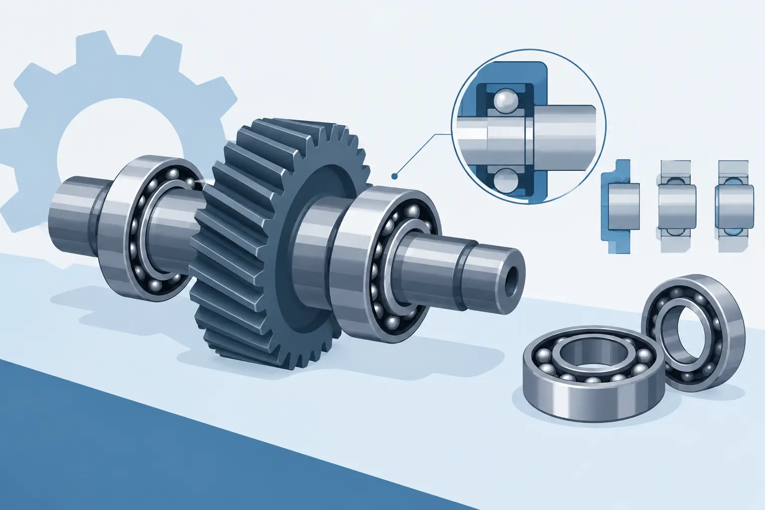
A gear shaft can have accurate tooth geometry, the correct centre distance and a well-sized bearing, then still fail because one ring is allowed to creep. Bearing fits for gear shafts are not a finishing detail. They determine whether load is transferred cleanly into the shaft and housing, whether internal clearance changes as intended, and whether the assembly can be built and serviced without damaging precision parts.
Start with the ring that rotates under load
The working rule is straightforward: a bearing ring subjected to a rotating load should normally have an interference fit on its seating. The fit prevents microscopic movement between the ring and its mating surface. That movement, known as creep, can fret the shaft or housing bore, generate heat and gradually destroy the locating geometry.
For a typical fixed-axis spur gear shaft, the inner ring rotates with the shaft while the radial gear force remains broadly fixed relative to the housing. The inner ring therefore sees a rotating load and usually needs interference on the shaft. The outer ring sees a stationary load and can often use a clearance or transition fit in the housing.
This changes when the load direction rotates, when the housing rotates, or when the shaft carries a planet gear. In planetary systems, the planet bearing arrangement and carrier motion can create load cases that are less intuitive than a conventional parallel-shaft gearbox. Establish the load direction relative to each ring before selecting tolerance classes.
Why gear loads make fit selection less forgiving
A gear does not apply a simple radial load. Spur gears create radial separating force and tangential torque force. Helical gears add axial force. Misalignment, tooth profile error, shock loading and reversing torque introduce further variation.
Those forces influence both bearing choice and fit. A shaft supporting a helical pinion with opposed angular-contact bearings may require a fit strategy that preserves preload and axial location. A slow, lightly loaded spur gear on deep-groove ball bearings may tolerate a more serviceable arrangement. The correct answer depends on load magnitude, duty cycle, shaft material, housing material, temperature and assembly method.
Do not specify a tighter fit merely because the gearbox is expected to work hard. Excessive interference can reduce bearing internal clearance, raise running torque and create unwanted preload. On a small bearing, a few microns matter. A fit has to resist creep without turning a free-running bearing into a heat source.
Interference changes internal clearance
Pressing an inner ring onto a shaft expands that ring. Pressing an outer ring into a housing compresses it. Both effects reduce internal radial clearance. If both rings receive substantial interference, the reduction can be significant enough to alter fatigue life and temperature behaviour.
This is particularly relevant for deep-groove ball bearings specified with normal clearance. Under a heavy shaft fit, a C3 clearance bearing may be appropriate, but it is not an automatic upgrade. The bearing manufacturer’s data should be used to calculate clearance reduction from the actual fit, bearing size, ring geometry and temperature difference.
For tapered roller and angular-contact bearings, the issue is usually expressed as endplay or preload rather than free internal clearance. Their fit selection must support the adjustment method. If axial positioning is set by shoulders, spacers and clamping nuts, the seating faces and shoulder geometry are as critical as the diameter tolerance.
Specify the shaft seat before the housing bore
Begin with the shaft because it commonly carries the rotating loaded ring. Define the nominal bearing bore, the seating length, the tolerance zone, surface finish and shoulder dimensions as one interface.
As a practical starting point, a shaft tolerance such as k6 may suit moderate loads where controlled assembly is still useful. Heavier loads, shock loads or a greater risk of ring creep can move the requirement towards m6 or n6. These are starting points, not universal prescriptions. The correct ISO tolerance class varies with bearing bore, bearing type, load ratio and whether the bearing has normal, increased or reduced clearance.
The shaft seat needs a suitable cylindrical finish and roundness. A nominally correct diameter is not enough if the seat is lobed, tapered or marked by a rough turning operation. The ring will conform to the errors, reducing raceway accuracy and increasing vibration. Avoid a keyway, cross-hole or abrupt section change directly beneath the bearing seat where possible.
Provide a proper shaft shoulder to locate the ring axially. Its height must clear the bearing chamfer, while its face should run square to the shaft axis. A generous fillet may strengthen the shaft, but if the radius exceeds the bearing chamfer it prevents the ring from seating fully. This is a frequent source of apparent axial play in compact gear assemblies.
Choose the housing fit around function and material
A stationary outer ring under stationary radial load is often located in an H7 housing bore. This supports straightforward assembly and allows the bearing to be replaced without machining damage. Where the outer ring experiences rotating load, vibration, shock or a tendency to walk in the bore, a transition or interference fit may be needed.
Housing material changes the decision. Aluminium housings expand more than steel housings as temperature rises. A fit that is adequate at room temperature may lose retention at operating temperature. Thin-walled housings also deform more readily during pressing, which can distort the outer ring and reduce running clearance.
For compact transmission housings, check the wall thickness around the bearing pocket, the distance to fasteners and any interrupted features such as split lines or access slots. The bore must remain round when the case is bolted together. A precisely modelled bearing seat is useful only if the physical housing can hold that shape under clamp load and operating temperature.
When serviceability matters, it can be better to retain an outer ring axially with a cover, circlip or shoulder rather than force a high interference fit into a light alloy housing. That choice adds parts and assembly steps, but it may protect an expensive housing from repeated bearing replacement.
Treat locating and floating bearings as an assembly decision
Many gear shafts use one locating bearing position and one floating position. The locating bearing controls axial shaft position. The floating bearing permits thermal growth without creating axial load in the bearing set.
The floating function is usually achieved by allowing one ring to move axially in its seat, commonly the outer ring in the housing. That ring may still need sufficient radial retention to avoid creep, so the arrangement requires care. A loose fit that solves thermal growth but permits bore fretting is not a successful floating design.
For helical gears, the axial force must have a defined path through the shaft, bearings and housing. Do not rely on an incidental press fit to react thrust. Select bearings and axial retaining features that are designed for the expected direction, including torque reversal if the drive can run both ways.
Build the fit into the full tolerance chain
A bearing fit cannot be selected in isolation from the gear location. The gear’s axial position, shoulder stack, spacer length, retaining nut, housing face and bearing width together establish mesh position and bearing loading.
For example, a helical gear may be correctly positioned on the shaft, but an overlong spacer can preload an angular-contact pair when the housing cover is tightened. Conversely, a missing controlled shoulder can leave the inner ring unsupported, allowing the clamping load to pass through the rolling elements during assembly.
Model the assembly geometry early. Show which bearing ring is pressed onto which component, where axial clamping occurs, and which dimensions control gear position. In GearSuite, bearing-fit guidance belongs alongside shaft, housing and gear geometry because these choices are connected, not separate CAD clean-up tasks.
Plan assembly before releasing the drawing
A fit that works on paper may be impractical at the bench. If an inner ring has interference on the shaft, apply force only through that inner ring during installation. Pressing through the outer ring transfers load through the rolling elements and can mark the raceways before the gearbox has run.
Thermal assembly can reduce risk for tighter fits. Heating a bearing with controlled equipment or cooling a shaft can provide the needed clearance without excessive press force. Keep the process controlled and clean. Open flames, uncontrolled heating and striking rings with a hammer are poor substitutes for a defined assembly method.
State the essentials on the production drawing: bearing designation, shaft-seat tolerance, housing-bore tolerance, surface finish where needed, shoulder and fillet limits, axial retention method and any preload or endplay requirement. A note such as “fit bearing as required” transfers an engineering decision to the workshop when it should already be resolved.
A well-chosen fit is rarely the most aggressive one. It is the one that holds each ring where it must stay, preserves the bearing’s intended operating condition and can still be assembled with real tools. Make that decision while the shaft, bearings and housing are visible together. It is cheaper than discovering a creeping ring after the gearbox is already built.