
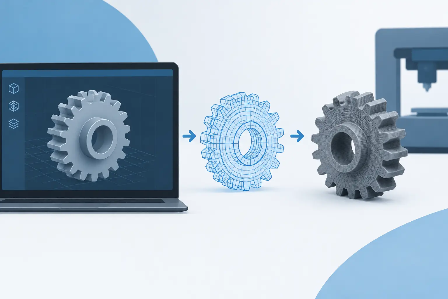
A gear that looks correct in a slicer can still be wrong where it matters: at the tooth flanks, on the shaft, inside the housing, or against the mating gear. An STL gear model generator should do more than create a circular part with teeth. It should help you define a mechanism that can mesh, mount and be manufactured.
For prototype shops, machine builders and product teams, the useful question is not simply, “Can this tool export an STL?” It is whether the generated mesh represents a controlled gear design with the right tooth system, centre distance, bores and clearances. Built for real parts means treating the STL as the result of engineering decisions, not the starting point.
What an STL gear model generator needs to produce
An STL is a triangulated surface mesh. It is widely accepted by slicers and many additive manufacturing workflows, but it contains no native feature history, dimensions or engineering intent. Once exported, a bore is only a set of triangles and a tooth profile is only a faceted surface. That makes the configuration stage critical.
A capable generator begins with gear geometry rather than decorative teeth. For a conventional spur pair, this means a true involute tooth form, selected through a consistent module, tooth count and pressure angle. The same inputs establish pitch diameters and the required centre distance. Change the tooth count or module, and the mating geometry must update with it.
Helical gears add another level of dependency. Helix angle, hand, face width and transverse geometry affect how the pair meshes and the axial loads it creates. A helical gear is not just a spur gear twisted through its thickness. If the generator cannot show the mating relationship and identify incompatible inputs, it is asking the user to discover the error after printing or machining.
The part also needs mechanical interfaces. Shaft bore diameter, keyway or flat, hub proportions, set-screw locations, root relief and face width can matter as much as the tooth count. For a printed test part, these features may be intentionally generous. For a functional assembly, they need to reflect the shaft, bearing arrangement and manufacturing method.
Configure from the mechanism, not from the STL
The fastest route to a bad gear is selecting a tooth count because it gives an appealing ratio, then forcing every other dimension around it. Start with the transmission requirement instead: speed reduction or increase, torque, available envelope, shaft centres and expected operating conditions.
For a simple pair, the ratio comes from the relationship between driver and driven tooth counts. But ratio alone does not define a usable set. A small pinion may introduce undercut, reduce root strength or become difficult to print cleanly. A large module may survive rough handling but exceed the available centre distance. A fine module may package neatly yet demand better printer calibration and post-processing.
Choose the tooth system deliberately. Module is the common metric basis for European mechanical work and determines tooth scale. Pressure angle influences tooth shape, contact behaviour and radial loading. Standard values simplify compatibility, but the correct selection still depends on the application. A low-load demonstrator and a compact actuator gearbox do not deserve the same assumptions.
Then define the assembly interfaces. Establish the centre distance, shaft diameter and bearing locations before finalising hubs and gear thickness. If the gear must sit beside a bearing, inside a housing or on a motor shaft, inspect those relationships in the same workspace. Isolated part generation is quick only until the first interference appears.
Print tolerances are part of the design
FDM, resin and powder-bed processes produce different results. A nominal 8 mm bore may print undersize on one machine and oversize on another. Horizontal holes, vertical holes, tooth tips and thin hubs all respond differently to orientation, material shrinkage and layer settings.
Use test coupons or known process allowances to set bore compensation and running clearance. For prototype drivetrains, it is often sensible to print a bore slightly undersize and finish it by reaming, particularly where concentricity matters. A press fit for a bearing needs a different allowance from a freely rotating shaft. The generator can provide nominal geometry; your production process determines the final compensation.
Tooth quality deserves the same attention. Coarse layers and poorly tuned extrusion can round tooth tips, fill root spaces and increase friction. Increasing module or reducing print layer height may improve mesh quality, but both choices have costs. The first changes packaging and ratio options; the second changes build time.
Inspect the assembly before export
A useful STL gear model generator should make decisions visible. Seeing two parts positioned at their calculated centre distance is more valuable than reading a diameter field in isolation. Live 3D inspection helps reveal obvious faults: an oversized hub crossing into a housing wall, a gear face colliding with a bearing, or a rack that cannot travel through its intended stroke.
Exploded views are equally practical. They expose stack-up order, show whether gears can be assembled onto shafts and make it easier to inspect interfaces that would otherwise be hidden. This is especially valuable in planetary gearboxes, where sun, planet and ring geometry must coexist with carrier pins, bearings and housing features.
Validation should cover more than whether a file can be created. Good engineering checks flag invalid tooth combinations, incompatible centre distances, impossible bearing fits and geometry that cannot assemble as configured. These checks do not replace duty-cycle calculations, lubrication design or physical testing. They do prevent basic configuration errors from reaching the workshop.
For rack-and-pinion systems, inspect travel and mounting position as well as mesh. The rack must have enough usable length, the pinion must clear its supports, and the chosen pressure angle must suit the matching profile. For cycloidal reducers, pay particular attention to eccentricity, pin arrangement, output interfaces and clearance around moving discs. These mechanisms are compact precisely because their geometry is closely coupled.
When STL is the right export format
STL is the practical choice when the immediate job is additive manufacture. It moves cleanly into slicer software, communicates external shape reliably and is usually enough for printed fit checks, enclosure trials and low-load prototypes. For makers building a one-off fixture or a proof-of-motion model, it may be the only export required.
It is not always the best handoff for downstream engineering. A machinist, tooling supplier or colleague editing the part in CAD will generally need a STEP file instead. STEP retains analytic surfaces and solids more effectively than a triangle mesh, making it more suitable for drawings, toleranced features, CAM preparation and modifications. DXF may be the appropriate output where a 2D gear outline, plate profile or laser-cut housing component is required.
The sensible workflow is therefore format-specific. Export STL for the printed part you need to test. Keep an editable production-oriented format available for the parts likely to be machined, revised or incorporated into a larger assembly. Do not expect an STL conversion to restore the design intent that was discarded at export.
A practical workflow for printable gear sets
Configure the transmission first, beginning with ratio, module, pressure angle, tooth counts and centre distance. Add face width, hubs, shaft bores and the surrounding constraints. Inspect the pair or mechanism in 3D, including bearings, shafts and housing clearances where those components govern the layout.
Run engineering checks before generating production files. Address warnings by changing the underlying parameters, not by scaling the mesh after export. Scaling an STL changes every dimension at once, including bores, centre distance assumptions and tooth size. It is rarely a controlled design correction.
Next, export an STL at suitable mesh quality and prepare it for the target printer. Orient the gear to protect critical surfaces and minimise support damage. Verify minimum wall thickness around bores and hubs. Print a single gear or a short section of the mechanism first when the fit is uncertain, then measure the result before committing to a full gearbox build.
GearSuite follows this mechanism-first approach across spur and helical pairs, planetary systems, cycloidal reducers and rack-and-pinion layouts. The aim is direct: configure assembly geometry, inspect it, validate it and export the format required for the next operation.
A printed gear is cheap to remake. A gearbox layout built around the wrong centre distance is not. Put the effort into the geometry while it is still parametric, then let the STL carry a design you have already checked.