
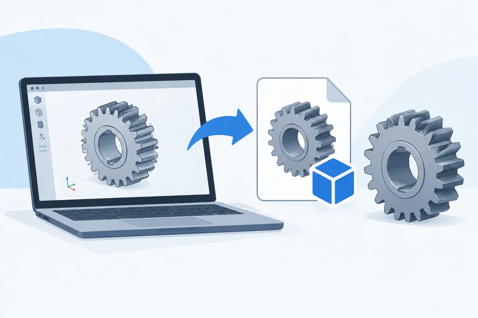
A gear can look correct in a viewport and still fail at the CAD handoff. Teeth may be simplified, a bore may be missing its keyway, or the receiving team may get individual solids with no clear assembly relationship. To export STEP files for gears properly, treat export as the final engineering check, not a download button.
STEP is the practical exchange format for manufacturing-oriented gear geometry. It carries solid bodies into the recipient's CAD, CAM or inspection workflow without asking them to rebuild tooth forms, shafts or interfaces. The value is not merely a file extension. It is the ability to hand over geometry that remains useful when it reaches a machinist, housing designer or prototype shop.
Start with the mechanism, not the gear blank
A standalone gear is rarely the whole design problem. Its tooth system must agree with the mating gear, while its bore, hub, face width and mounting features must suit the shaft and manufacturing route. If the gear belongs in a planetary stage, rack drive or reduction gearbox, its position relative to every connected component matters as much as its outside diameter.
Configure the transmission before preparing the export. Set the module or diametral pitch convention required by the project, pressure angle, tooth counts, helix angle where applicable, face widths and centre distance. For helical pairs, confirm that handedness and helix angles are complementary. For planetary systems, confirm the tooth-count relationship and planet placement rather than assuming a visually plausible layout will assemble.
This is where a mechanism-specific workflow saves time. True involute teeth are generated from the selected parameters, so the pitch relationship is tied to the geometry you inspect. A generic CAD model of a toothed disc may be useful for a placeholder, but it is not a substitute for production geometry.
Inspect the geometry before STEP export
Exported geometry preserves what you have designed, including mistakes. Use the 3D assembly view to look beyond the tooth mesh. Rotate the mechanism and inspect the areas that frequently create downstream rework: bore transitions, hub clearances, shaft shoulders, bearing seats, retaining features and housing walls.
For a spur gear pair, check that the teeth engage across the intended face width and that the shafts sit at the defined centre distance. For a helical pair, inspect axial positioning as well as meshing. Helical gears introduce axial load, so a model that clears visually may still need bearing and shoulder decisions that support the intended thrust direction.
Exploded inspection is equally useful. It exposes whether parts are genuinely separate solids, whether a bearing interface has been accounted for, and whether the assembly order makes physical sense. A STEP file cannot explain an ambiguous assembly as effectively as a deliberate model can.
Before export, check these four areas:
- Tooth geometry: correct module, pressure angle, tooth count, profile shift where used, and compatible mating form.
- Functional interfaces: bore diameter, keyway or spline details, set-screw locations, hub proportions and shaft seating faces.
- Manufacturing clearance: root fillets, undercut risk, tool access, wall thickness and clearance around adjacent parts.
- Assembly references: centre distance, axial spacing, bearing positions and the orientation of each component.
The exact checks depend on the application. A laser-cut prototype gear may tolerate a simpler hub arrangement than a steel gear intended for a keyed motor shaft. A printed housing may need more clearance than a machined one. Keep the functional geometry fixed, then adapt the surrounding details to the process.
Choose the right export scope
The most useful STEP export is not always the largest one. Exporting every part in a complete gearbox is valuable when another engineer needs to design the enclosure, machine shafts or review interference. It can be unnecessary when a supplier only needs a single driven gear for quotation.
For a component order, export the individual gear with its complete functional features. The recipient should receive the tooth form, bore, hub and any required keyway, fixing pattern or recess. Do not send a decorative outer profile and expect the shop to infer the rest.
For integration work, export the assembly geometry. Include the mating gear and relevant shafts, bearings or housing reference geometry where permitted by the workflow. This allows the receiving designer to locate bores, shoulder faces and envelope clearances without recreating the drivetrain from dimensions in an email.
There is a trade-off. An assembly STEP provides context but can be heavier and more complex in the receiving CAD system. Separate part files are easier to manage for manufacture, but they lose positional information. Where both are needed, provide the complete assembly export alongside clearly named component exports. The assembly remains the spatial reference; the individual files remain the production parts.
Preserve useful detail, not unnecessary complexity
A manufacturing file needs enough detail to define the part. It does not need every cosmetic feature or experimental variant from the design session. Remove duplicate bodies, hidden trial parts and geometry that is not intended to be made. Confirm that only the final configuration is active before exporting.
Do not simplify involute teeth into approximate triangular forms merely to make a file smaller. That defeats the purpose of a STEP handoff for gears. Tooth profile, root transition and face geometry affect contact, tooling and fit. Simplification is appropriate only when the model is explicitly being used as a spatial envelope, such as checking whether a motor clears a housing.
Likewise, be deliberate about small features. A keyway, retaining-ring groove or threaded hole can be essential. A tiny embossed label is usually not. The distinction is functional intent. Useful detail by default means the features needed to make, mount or inspect the part are present and readable.
Validate the exported file in the receiving context
A successful export message is not full validation. Open the STEP file in a second CAD viewer or the target CAD package when possible. Confirm that the body arrives as a solid, not a surface shell or faceted mesh. Check the unit interpretation, overall diameter, face width and bore size with a measurement tool.
Then inspect the tooth region closely. Circular edges and involute flanks should be clean enough for the recipient's system to recognise the shape as manufactured geometry. Depending on the software and the receiver's needs, STEP export settings and supported application protocols can influence how metadata and assembly structure are carried. Geometry compatibility is the priority, so test the path that your shop, customer or CAM package actually uses.
For an assembly, verify that component positions survive the handoff. Some systems import solids correctly but treat the assembly as a collection of unstructured bodies. That may be acceptable for machining or interference review, but it is less useful for a team that needs a bill of materials or editable component hierarchy. Ask what the recipient needs before selecting the export scope.
Name files for the workshop, not just the browser
File names become part of the manufacturing record. A name such as `gear_final_v7.step` is understandable for an afternoon but unhelpful six months later. Use a convention that identifies the project, component, revision and key configuration where relevant. For example, a file name can distinguish a 24-tooth pinion from a 48-tooth gear without forcing someone to open each model.
Keep revision control equally clear. If you alter the module, tooth count, bore or face width, that is not a cosmetic update. It changes a functional part and should receive a new revision. Avoid overwriting a file already released for quotation or manufacture. The cost of one extra export is lower than the cost of cutting an obsolete gear.
GearSuite is built around this sequence: configure the transmission, inspect the assembly geometry, run engineering checks, then export manufacturable solids. The purpose is direct handoff, not another generic modelling task.
Make the handoff explicit
A STEP file defines geometry, but it does not replace engineering communication. State the intended material, process, heat treatment, tolerance requirements and any tooth-quality specification outside the geometry file where the job requires them. A gear shop cannot derive a full inspection plan from a solid alone.
For prototype work, a concise note identifying the mating component, target backlash approach and intended shaft fit can prevent expensive assumptions. For production work, drawing dimensions and GD&T may still be required. STEP carries the model; controlled documentation carries the acceptance criteria.
The best export is the one that lets the next person make a decision without rebuilding your design. Give them true gear geometry, the interfaces that matter and enough assembly context to see how the part earns its place. That is a file ready for real parts.