
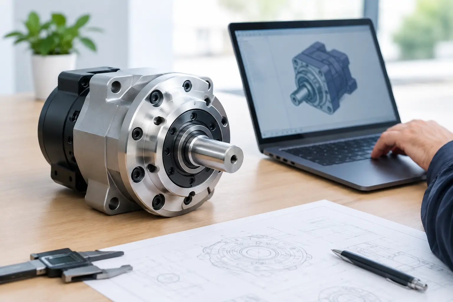
A 30:1 cycloidal stage can appear convincing long before it is buildable. The ratio may be correct, the disc may rotate in a CAD viewport, and yet the eccentric bearing has no viable seat, the output pins collide at assembly, or the housing leaves no tolerance for the ring pins. A proper cycloidal reducer design calculator has to work beyond ratio arithmetic. It must turn a drivetrain requirement into coordinated, inspectable assembly geometry.
That distinction matters when the mechanism is expected to carry torque rather than serve as an animation. Cycloidal reducers are compact, tolerant of shock loading, and capable of high reductions in one stage. They also concentrate several design decisions into a small envelope: pin count, lobe geometry, eccentricity, bearing selection, output carrier arrangement, shaft interfaces and housing stiffness. Change one value and several others may no longer fit.
What a cycloidal reducer design calculator should solve
At its simplest, a cycloidal reducer uses an eccentric input to orbit a lobed disc inside a fixed circle of ring pins or rollers. The disc profile has one fewer lobe than the pin count in a common single-disc arrangement. As the disc precesses, output pins transmit the slow rotation to an output flange.
This produces a large reduction in a compact package, but the familiar pin-count rule is only the start. The exact ratio depends on the chosen kinematic arrangement and output convention. A calculator should state the resulting ratio and rotation direction clearly rather than leave users to infer them from a sketch. If a design needs 29:1, 31:1 or a ratio tied to an available motor speed, the pin and lobe counts must be selected with the entire assembly in view.
The same applies to geometry. Ring-pin pitch diameter, pin diameter, eccentricity and disc thickness are coupled variables. Larger pins can improve contact area and durability, but reduce the available space between pins and may demand a larger housing. Increasing eccentricity can make the mechanism physically larger and alter the profile shape, while reducing it too far can create impractical features or leave insufficient movement for the intended output-pin pattern.
A useful calculator therefore generates the actual disc profile, not a symbolic outline. The profile must account for the rolling or contact geometry against the ring pins and for the intended clearance. It should be visible in 3D with the pins, eccentric, output plate and housing boundaries present. Built for real parts means the disc is assessed as a solid that must be machined, printed or otherwise manufactured, not merely as a curve that satisfies a ratio equation.
Ratio is a requirement, not a complete specification
Start from the load case: required output speed, input speed, continuous torque, peak torque, duty cycle and permitted envelope. A high nominal ratio is not automatically the right choice. A single cycloidal stage can provide substantial reduction, but a very high ratio may require a pin count that makes the mechanism larger than expected or leaves unfavourable proportions for the selected pins and bearings.
There is also a practical trade-off between a single disc and a dual-disc layout. Two discs phased relative to one another can improve balance and distribute load, but add parts, axial length and assembly detail. For a lightweight prototype, a single disc may be appropriate. For a machine axis or continuous-duty actuator, the extra complexity can be justified by smoother operation and reduced eccentric reaction.
A calculator should allow these choices to remain explicit. Hiding them behind a single ratio field produces a mechanism that may be mathematically valid but mechanically underdefined.
Configure the geometry from the load path
The load path in a cycloidal reducer is more informative than the outer diameter. Torque arrives at the input shaft, drives the eccentric, loads the eccentric bearing, transfers through the cycloidal disc into ring pins, then reaches the output through output pins or rollers. Each interface needs dimensions that can coexist.
Begin with the ring-pin arrangement. The calculator should set the pin count and pitch circle, then establish pin diameter and usable engagement. The disc profile follows from these values and the eccentricity. At this stage, inspect the narrowest regions of the disc. Thin lobes may be difficult to manufacture accurately and can become weak points under repeated contact loading.
Next, place the eccentric bearing and input shaft. Bearing-fit guidance is valuable here because the eccentric introduces radial load and creates a local packaging problem. The shaft diameter must suit torque transmission and the bearing bore, while the bearing outside diameter must leave material in the disc and clearance from adjacent output features. A nominally compact reducer can fail at this point because the required bearing is simply too large for the chosen pin circle.
Then define the output pins, their pitch circle and their fit in the cycloidal disc holes. These holes are not decorative. Their diameter, clearance and location influence backlash, local stress and assembly. Pins that are too close to the disc edge can leave a fragile bridge of material. Pins that are oversized or insufficiently spaced may clash with the eccentric bearing or ring-pin region.
Finally, develop the housing around the operating mechanism. The housing must locate ring pins accurately, support bearings, retain lubrication where relevant and provide fastener land. A calculator that shows only the disc cannot expose whether a wall is too thin, a bearing shoulder is missing or a motor mounting face conflicts with the input shaft.
Validate constraints before generating production files
Constraint validation is where a mechanism-specific tool earns its place over general CAD. General CAD will let users model intersecting solids, impossible press fits and unsupported bearing arrangements unless they manually check every relationship. A cycloidal workflow should identify problems while parameters are still easy to change.
The essential checks include interference through the full orbit of the disc, minimum material thickness around lobes and output holes, ring-pin spacing, bearing-seat compatibility, shaft clearances and housing-wall feasibility. It should also show assembly geometry in exploded view. A reducer can be interference-free in its final position yet impossible to assemble because pins cannot be inserted after a shoulder or cover is in place.
Clearance deserves particular care. The correct value depends on manufacturing process, material, reducer size and intended duty. A resin-printed demonstrator and a steel-pinned aluminium housing do not share the same assumptions. Too little clearance can cause binding as dimensional variation accumulates. Too much can increase backlash, impact loading and noise. The right calculator makes the chosen clearance visible in the geometry, so it can be judged against the fabrication method rather than treated as an abstract number.
Do not confuse geometric clearance with a complete durability calculation. Contact stress, bearing life, pin material, lubrication, thermal behaviour and fatigue require assumptions about load and use. For demanding applications, validate those separately against the intended materials and operating conditions. Geometry validation prevents avoidable layout errors; it does not repeal the need for engineering judgement.
Inspect motion, then export connected parts
Before export, rotate the mechanism through its operating cycle. Watch the disc orbit relative to every ring pin, inspect the output-pin engagement and check the eccentric and output shaft positions. A live 3D view is not just presentation. It is a fast way to identify an incorrect rotation convention, a missed collision or a component that appears disconnected once the assembly moves.
The final hand-off should preserve the design intent. Manufacturing teams need individual solids for discs, pins, shafts, housings and covers, along with dimensions that remain coherent across the mechanism. STEP is typically the useful hand-off for editable solid geometry, while STL may suit additive manufacture and DXF can support profile-based processes where appropriate. Exporting isolated shapes without the surrounding assembly context merely moves the coordination problem downstream.
GearSuite is designed around that connected workflow: configure the cycloidal stage, inspect the mechanism and exploded assembly, validate key constraints, then export production-oriented geometry. Decisions stay visible, including the component relationships that generic modelling workflows often leave to manual reconstruction.
A cycloidal reducer is most successful when its ratio, contact geometry, bearings and housing are treated as one system. Choose parameters that fit the real load path, validate the assembly before cutting material, and let the calculator expose compromises while they are still inexpensive to correct.