
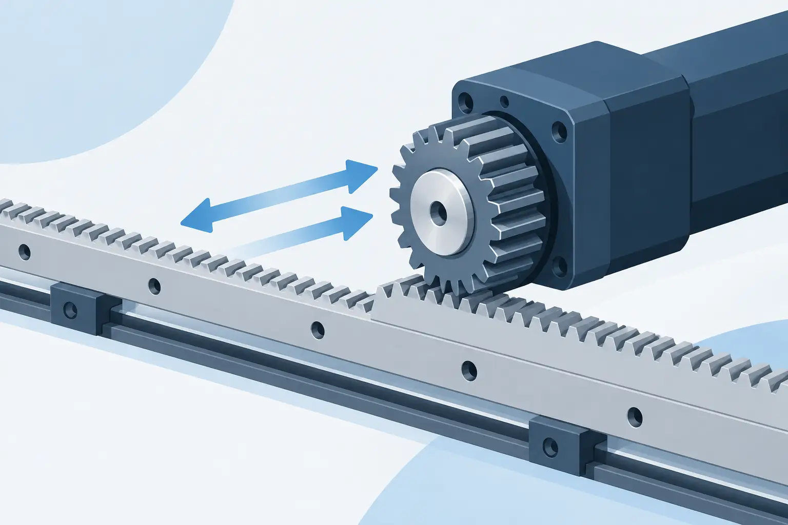
A rack pinion mechanism can look deceptively simple: a circular gear drives a straight toothed bar, turning motor rotation into linear travel. Yet the difference between a moving prototype and a reliable machine axis is usually decided by details outside the basic ratio - tooth standard, mounting stiffness, backlash, bearing support and how the rack is referenced along its full length.
For machine builders, product developers and prototype shops, the question is not whether a rack and pinion will move. It is whether it will move accurately, carry load without excessive wear, remain quiet enough for the application and be practical to manufacture and assemble.
What a rack pinion mechanism actually does
A pinion is a gear with a defined number of teeth. A rack is effectively a gear with an infinite pitch diameter: its teeth are arranged along a straight pitch line rather than around a circle. When compatible teeth mesh, every pinion revolution produces a fixed linear displacement.
For a metric involute system, the linear travel per pinion revolution is:
`travel = π × module × number of pinion teeth`
A module 2 pinion with 20 teeth therefore advances the rack by approximately 125.66 mm per revolution. This direct relationship is one reason rack drives are useful where a rotary motor must create long linear travel without a screw becoming impractically long.
The ratio is only the starting point. A larger pinion gives more travel per revolution and generally allows higher linear speed at a given motor speed. It also reduces output force for the same motor torque. A smaller pinion increases linear force but can create a less favourable tooth engagement condition, particularly if tooth count falls too low.
Start with motion, load and resolution
Define the axis before selecting teeth. Required stroke, peak speed, acceleration, duty cycle and external load determine whether a rack drive is appropriate and what scale it needs to be. A light camera slider and a moving gantry for a router may both use rack-and-pinion motion, but their stiffness, contamination and force requirements are very different.
The ideal linear force can be approximated from torque divided by the pinion pitch radius. In real assemblies, losses from bearings, seals, guideways and tooth friction must be included. Acceleration also matters. A drive that can sustain a static load may still lack the torque to accelerate the moving mass at the required rate.
Resolution follows from motor and control choices. If a stepper motor has 200 full steps per revolution, each full step moves the rack by the pinion circumference divided by 200. Microstepping can refine command resolution, but it does not remove backlash, flex or tooth-spacing error. Do not treat controller increments as guaranteed positioning accuracy.
Select a tooth system before modelling parts
Rack and pinion teeth must share the same module and pressure angle. In metric machinery, 20-degree pressure angle involute teeth are a common and practical choice. The rack module must match the pinion module exactly. A module 1.5 pinion will not mesh correctly with a module 2 rack, regardless of apparent tooth size.
Face width should reflect load, stiffness and manufacturing capability. More width can distribute load across more tooth surface, but only when alignment is controlled. A wide pinion on a flexible carriage can contact heavily at one edge, increasing wear rather than improving capacity.
Helical racks and pinions can offer smoother engagement and higher overlap than spur teeth. They also introduce axial force, which must be reacted through suitable bearings and housing geometry. For compact, straightforward mechanisms, spur systems are often easier to package, inspect and manufacture. For faster or quieter axes, the extra complexity of a helical design may be justified.
Backlash is an assembly problem as well as a gear problem
Backlash is the clearance between mating tooth flanks. Some clearance is needed for lubrication, thermal expansion and tolerances. Too much creates lost motion when direction changes. Too little risks tight spots, noise and rapid tooth damage.
A fixed single-pinion arrangement usually has measurable backlash. For simple material handling, sliding gates or manually positioned fixtures, that may be entirely acceptable. For a router, pick-and-place axis or inspection system, reversal error may be unacceptable unless the control strategy and mechanical arrangement account for it.
Preloaded dual-pinion designs are a common response. Two pinions are biased in opposite rotational directions so that each contacts a different rack flank. Spring preload can accommodate small errors, while torsional or split-pinion arrangements can provide a more controlled preload. The trade-off is increased friction, greater component count and a more demanding assembly process.
A gearbox can also contribute backlash. Reducing rack clearance while ignoring planetary gearbox clearance simply moves the positioning error upstream. Treat the motor, gearbox, coupling, pinion shaft, bearings, rack and guideway as one motion chain. Decisions stay visible when the whole chain is considered.
Mounting determines whether the teeth survive
The rack needs a stable datum surface. Its mounting face and locating shoulder should control position, while bolts provide clamp force. Using bolts alone to locate a long rack can allow small shifts during tightening and makes repeatable replacement harder.
For long axes, racks are often installed in sections. The joint between sections needs as much care as the tooth profile itself. A poor joint can create a pitch discontinuity that is felt as a bump, noise or local overload every time the pinion crosses it. Use a controlled joining method, inspect tooth alignment and support the rack consistently beneath the joint.
Pinion shaft support is equally important. A pinion mounted directly on a motor shaft may be suitable for low loads and short duty cycles. Higher loads or belt-driven arrangements benefit from a dedicated shaft supported by bearings close to the gear. Overhung pinions bend shafts and load motor bearings, causing uneven tooth contact.
The linear guideway must resist the forces generated at the gear mesh. Because the pinion applies force away from the guide bearings, it can create a moment that twists the carriage. If the carriage rotates slightly under load, mesh depth changes and the drive alternates between loose and tight. No amount of tooth calculation corrects an insufficiently stiff structure.
Lubrication and environment are design inputs
Open rack drives are exposed. Dust, chips, abrasive slurry and washdown conditions can shorten their life quickly. Choose the rack material, surface finish and lubrication method for the working environment rather than assuming a general-purpose grease will suit every application.
Grease often works well for moderate-speed, protected mechanisms, but it can hold abrasive particles in dirty environments. Oil systems may improve high-speed performance but need containment and maintenance provisions. Dry-running engineering polymers can be useful in clean, low-load applications, though they have their own limits in temperature, stiffness and long-term dimensional stability.
Consider how the mechanism will be serviced. Can the rack be cleaned without removing surrounding guards? Can the pinion be inspected? Is lubrication accessible after the machine is assembled? Service access is not a finishing detail. It affects whether the designed life is achievable in use.
Configure, inspect, validate, export
A productive design workflow connects tooth geometry to the parts that carry it. Start by configuring module, pressure angle, tooth count, face width, rack length and shaft interfaces. Then inspect the assembly geometry in 3D, including motor placement, bearing positions, carriage clearance and housing walls.
Validation should identify obvious infeasible choices early: inadequate root clearance, unsuitable shaft diameters, bearing-fit conflicts or geometry that cannot be exported as a useful manufactured part. The aim is not to replace detailed machine analysis where it is required. It is to prevent standard transmission decisions from becoming hidden CAD rework.
GearSuite is built around this mechanism-level workflow, combining true involute geometry with visible shafts, bearings, motor interfaces and manufacturable solids. For a rack drive, that means checking more than whether a circular gear touches a straight row of teeth. It means producing assembly geometry that can move towards a prototype or production hand-off with fewer assumptions.
When rack and pinion is not the best choice
Rack drives are strong candidates for long travel, high speed and applications where modular extension matters. They are not automatically the best choice for every linear axis. Ball screws can provide excellent precision and stiffness over moderate lengths, although critical speed and screw whip become limiting factors as travel increases. Belt drives are light, quiet and economical, but may lack the stiffness needed for high cutting forces. Linear motors remove mechanical contact at the drive interface but demand more from control, thermal design and cost.
Choose the mechanism that matches the required force, travel, accuracy, environment and service model. A rack-and-pinion axis earns its place when its advantages are designed into the whole assembly, not just calculated from its pitch diameter.
The practical test is simple: if the rack, pinion, bearings, guideway and structure can be inspected as one buildable system, the motion will be easier to trust when it leaves the screen.