
Backlash is not a number to add at the end of a gear design. It is clearance that has to survive the full assembly: manufactured tooth thickness, centre-distance variation, bearing play, housing movement and temperature. Knowing how to calculate spur gear backlash lets you specify a mesh that turns freely without becoming noisy, imprecise or prone to impact loading.
For a real mechanism, calculate backlash at the operating pitch circle and in the transverse plane. Spur gears make this more direct than helical gears because there is no helix-angle conversion, but the design decision still depends on the complete assembly geometry rather than the gear pair alone.
What backlash means in a spur gear mesh
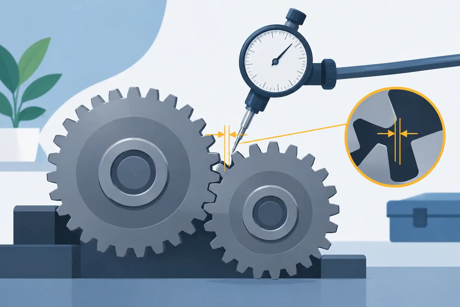
Spur gear backlash is the circumferential clearance between the non-driving flanks of two meshing teeth. Hold one gear still, reverse the other gently, and the angular movement before the teeth contact on the opposite flank is the visible result of backlash.
It is usually expressed as tangential or circular backlash, \(j_t\), in millimetres at the working pitch circle. Angular backlash can also be useful for positioning systems, but tangential backlash is the better starting point for gear design because it connects directly to tooth thickness and manufacturing tolerances.
Do not confuse backlash with root clearance. Root clearance is the radial gap between a tooth tip and the mating tooth root. It prevents interference at the tooth bottom. Backlash is flank clearance. A mesh can have adequate root clearance and still have too little or too much backlash.
The basic spur gear backlash equation
For an external spur gear pair, transverse backlash at the operating pitch circle is:
\[ j_t = p_{tw} - (s_{1w} + s_{2w}) \]
Where:
- \(j_t\) is transverse circular backlash
- \(p_{tw}\) is the operating transverse circular pitch
- \(s_{1w}\) and \(s_{2w}\) are the tooth thicknesses of gears one and two, evaluated at the operating pitch circle
This equation states the physical condition plainly: the available tooth space, less the combined thickness of the two mating tooth flanks, is backlash.
For standard gears mounted at their nominal centre distance, a useful reference is the transverse circular pitch:
\[ p_t = \pi m \]
Here, \(m\) is the module in millimetres. A standard, unmodified gear has nominal pitch-circle tooth thickness close to half the circular pitch:
\[ s = \frac{\pi m}{2} \]
If both gears are made at exactly nominal tooth thickness and mounted at exact nominal centre distance, the theoretical backlash is zero. That is a mathematical reference, not a production specification. Real gear pairs require intentional allowance.
Nominal centre distance
For two external spur gears with tooth counts \(z_1\) and \(z_2\), nominal centre distance is:
\[ a_0 = \frac{m(z_1 + z_2)}{2} \]
This applies to gears with the same module and pressure angle. If the actual operating centre distance \(a_w\) differs from \(a_0\), the working pressure angle changes. For standard involute gears:
\[ \cos \alpha_w = \frac{a_0 \cos \alpha}{a_w} \]
Where \(\alpha\) is the reference pressure angle and \(\alpha_w\) is the working pressure angle. Use the operating geometry when calculating the direct tooth-space equation. Mixing nominal pitch-circle values with operating centre-distance values gives a misleading backlash result.
A practical way to calculate spur gear backlash
In most design work, it is more useful to budget backlash than to derive every involute arc by hand. Start with the intended operating centre distance, then account for each source that opens or closes the mesh.
A small increase in centre distance produces an approximate increase in transverse backlash of:
\[ \Delta j_t \approx 2\Delta a\tan \alpha \]
Where \(\Delta a = a_w - a_0\). This approximation is accurate enough for early sizing and tolerance allocation when centre-distance changes are small. For final production geometry, use the actual working pressure angle and true involute tooth form.
Tooth thinning also increases backlash. If each gear tooth is reduced by a specified tangential amount, the total contribution is approximately the sum of both reductions:
\[ j_{tooth} = e_1 + e_2 \]
The practical estimate becomes:
\[ j_{total} \approx 2\Delta a\tan \alpha + e_1 + e_2 \]
This is a budget equation. It is useful while setting tolerances, not a reason to double-count effects. If you have already calculated backlash directly from the final operating tooth thicknesses and operating pitch geometry, do not add centre-distance and tooth-thinning terms again.
Worked example
Take a 20-tooth pinion and a 40-tooth gear, both module 2 mm with a 20° pressure angle.
The nominal centre distance is:
\[ a_0 = \frac{2(20 + 40)}{2} = 60\text{ mm} \]
Assume the housing places the shafts at 60.10 mm. Centre-distance increase is therefore 0.10 mm. The backlash created by that increase is approximately:
\[ 2 \times 0.10 \times \tan 20° = 0.0728\text{ mm} \]
Now assume the manufacturing specification thins each gear by 0.02 mm at the relevant measurement diameter. The tooth-thickness contribution is 0.04 mm.
The estimated transverse backlash is:
\[ j_{total} = 0.0728 + 0.0400 = 0.1128\text{ mm} \]
Rounded for engineering use, this mesh has about 0.11 mm of tangential backlash. Whether that is acceptable depends on the mechanism. It may be entirely reasonable in a compact drive or hand-operated mechanism. It may be excessive in an indexing axis where output motion must reverse with minimal lost movement.
Convert tangential backlash to angular backlash when needed
For a positioning mechanism, tangential clearance alone does not show the output error. Convert it to angular backlash at the gear of interest using its working pitch radius \(r_w\):
\[ \theta = \frac{j_t}{r_w} \]
The result is in radians. Multiply by \(180/\pi\) for degrees.
For the 40-tooth module 2 gear in the example, the nominal pitch radius is 40 mm. A 0.113 mm tangential backlash corresponds approximately to:
\[ \theta = \frac{0.113}{40} = 0.00283\text{ radians} \approx 0.162° \]
This is why a backlash value that looks small in millimetres can matter in a high-ratio positioning system. The same clearance is less significant in a fast rotary drive than in a camera pan mechanism, dosing system or actuator with repeated reversal.
Set the target from the mechanism, not a generic table
There is no universal correct backlash value. The required range depends on speed, load direction, lubrication, tooth size, material, manufacturing process, temperature and shaft support.
Plastic gears usually need more allowance than steel gears because mould shrinkage, moisture effects and thermal expansion can alter the running mesh. A printed prototype may need still more, particularly where tooth flanks are rough or dimensions vary by print orientation. Conversely, a tightly controlled steel gear pair in a rigid, accurately bored housing can run with far less backlash, provided thermal growth and alignment have been assessed.
Bearing selection matters as much as nominal centre distance. Radial bearing clearance, flexible bearing seats and a thin housing wall can move the shaft centres under load. If the drive reverses, those movements can appear as lost motion even when the measured static tooth backlash is modest. Gear geometry, shaft stiffness, bearing fits and housing tolerances need to be treated as one assembly decision.
Check backlash through the full design workflow
Configure the gear pair with a consistent module, pressure angle and tooth count. Set the intended centre distance rather than assuming the theoretical value. Then inspect the tooth mesh at the operating position, including any profile shift or non-standard tooth-thickness adjustment.
Next, validate the surrounding assembly. Check shaft locations, bearing bores, shoulder positions and housing features that establish centre distance. A precise gear model cannot compensate for an unconstrained bearing seat or a housing that changes shape when fastened.
Finally, export geometry only after the mechanism has been checked in its production state. GearSuite supports this workflow by keeping true involute gear geometry, assembly placement and manufacturable solids visible together. Decisions stay visible, which is where backlash belongs.
Use the calculation to define an allowance, then verify it on the part that will actually be made. Measure tooth thickness or span, confirm assembled centre distance, and turn the mechanism through several positions. A backlash value is useful only when it reflects the real teeth, real bearings and real housing that will carry the load.