
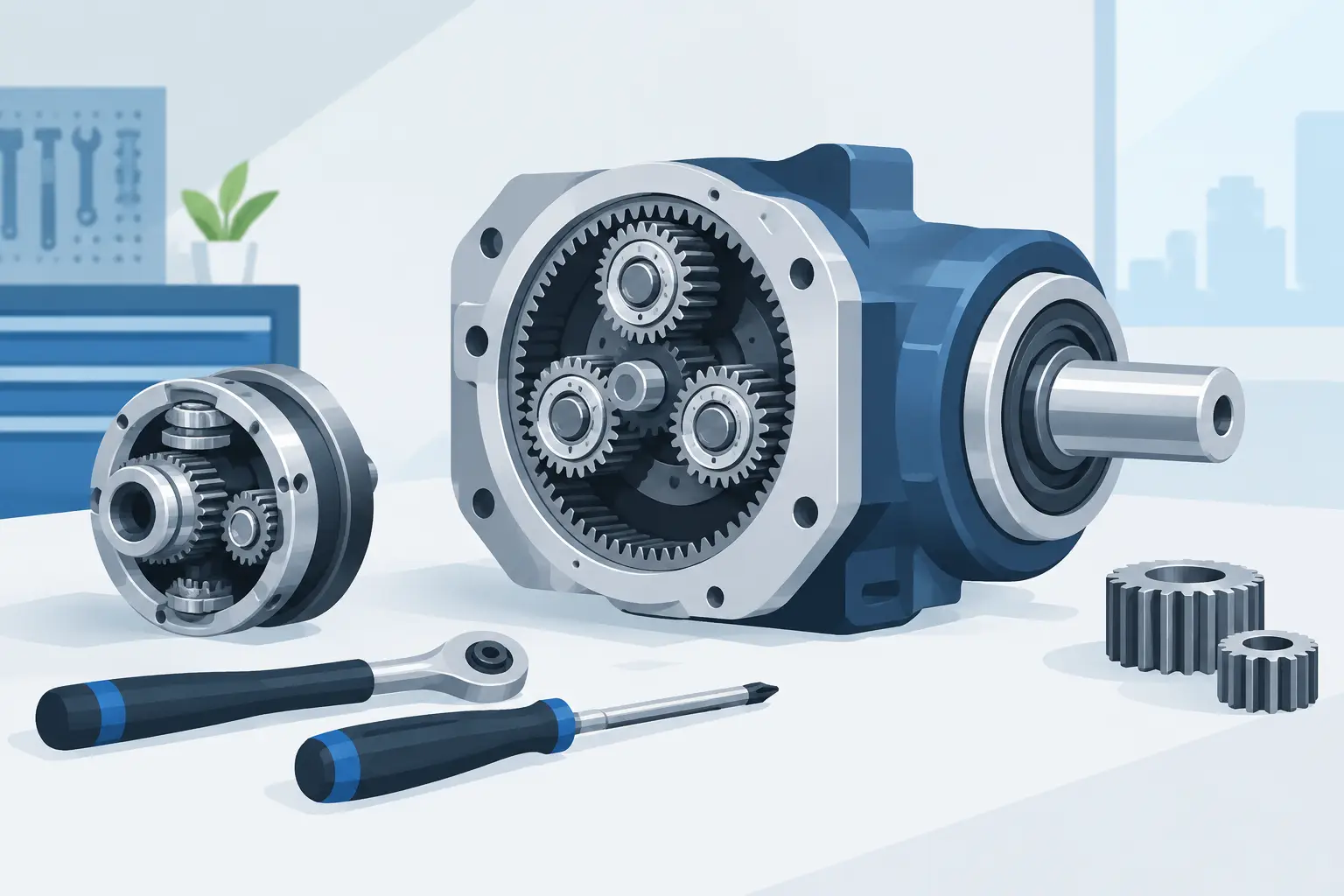
A planetary reducer rarely fails because someone forgot the ratio formula. It fails because a correct ratio was treated as a complete design. The sun gear may not accept the intended shaft, planets may collide with their pins or bearings, the ring gear may leave too little housing wall, or the carrier may be impossible to machine. Planetary gearbox tools should expose those dependencies while there is still time to change the architecture.
For makers and engineering teams, the useful question is not whether a tool can draw a sun, planet and ring. It is whether it can turn a drivetrain decision into assembly geometry that can be inspected, checked and handed to manufacturing.
What planetary gearbox tools need to solve
A simple calculator can provide a reduction value from sun and ring tooth counts. That is a useful starting point, but a planetary stage is constrained by geometry as much as kinematics. In a standard internal-gear arrangement, the ring tooth count must relate correctly to the sun and planet tooth counts. The centre distance between sun and planet must agree with the planet-to-ring mesh. If several planets are required, their angular spacing must also be compatible with the tooth count.
Those conditions determine whether the gears can physically mesh. They do not yet determine whether the mechanism can be built.
A production-oriented workflow must carry the calculation into real parts: true involute tooth profiles, gear face widths, bore diameters, planet pins, bearing seats, carrier plates, ring support, housing interfaces and output geometry. Each choice affects another. Increasing module can improve tooth strength, for example, but it also increases package diameter. Adding face width can improve load capacity, but may create a carrier or bearing arrangement that no longer fits the available axial length.
Useful tools keep these decisions connected rather than scattering them across a spreadsheet, a gear calculator and a general CAD assembly.
Configure the transmission before modelling details
Start with the operating architecture. Define which member is driven, which is held and which provides output. A fixed ring with sun input and carrier output gives the familiar reduction stage, but the same gear set behaves differently when the carrier is fixed or the ring is the output. The ratio is only meaningful when the fixed member and direction of rotation are explicit.
Next, establish the torque, input speed, target output speed and envelope. These values guide the first choice of module, tooth count range and face width. They also prevent a common mistake: pursuing a high ratio in a single stage when the resulting ring diameter, tooth loading or efficiency is unsuitable. A two-stage planetary arrangement may be larger axially, yet easier to manufacture and more credible under load.
Then set the gear standard and geometry. Pressure angle, module, helix angle where applicable, backlash and profile adjustments are not cosmetic settings. They define the tooth form and influence interference, contact conditions and centre distances. A tool that generates only symbolic cylinders and simplified teeth cannot give dependable feedback on a real gear set.
At this stage, parameter-driven planetary gearbox tools earn their place. Change the ratio target or package limit, and dependent geometry should update with it. The designer can compare options quickly without rebuilding each sun gear, planet, ring and carrier from scratch.
Planet count is an assembly decision
More planets can share load, but they introduce spacing, timing and carrier complexity. Three planets are a practical starting point for many compact reducers because they provide balanced loading without excessive carrier detail. Four or more may be appropriate for higher torque, but only if the tooth-count relationship permits equal spacing and there is room for pins, bearings and carrier webs.
Do not choose planet count from a load-sharing assumption alone. Manufacturing tolerance, carrier stiffness and bearing play affect how evenly planets actually share load. A compact stage with fewer, well-supported planets can be the better engineering choice.
Inspect the parts that calculators leave out
Once the transmission geometry is viable, inspect the assembly as parts rather than as a diagram. The planet gear is particularly revealing. It needs enough bore diameter for a pin or bearing arrangement, sufficient material around that bore, adequate clearance to the carrier, and a face width that aligns with the sun and ring.
The ring gear needs equal scrutiny. An internal gear may be integrated into a housing, retained as a separate machined component or manufactured by another process. Each route changes the required wall thickness, fixing features and tolerances. A ring that looks compact on screen may be impractical once its outer support geometry is included.
The carrier is often the component that decides whether a concept is credible. It must locate planet pins accurately, resist bending, clear the sun shaft and connect to the output. Split carriers can simplify assembly; one-piece carriers can improve alignment. Neither is universally better. The right choice depends on machining access, bearing retention, assembly sequence and the expected load path.
Live 3D and exploded views are valuable here because they make interfaces visible. Inspect the stack-up from input to output: motor interface, input shaft, sun gear, planet support, carrier, output bearing and housing. If a component cannot be inserted, retained or serviced in the intended order, the mechanism is not ready simply because the gears mesh.
Validate constraints early, not after export
Engineering checks should guide configuration, not appear as a late warning after detailed CAD work. Begin with basic meshing feasibility and planet spacing. Then evaluate clearances between gears, pins, bearings, carrier plates and housing walls. Verify that bores and shaft diameters are realistic for the selected gear size, and that bearing seats have enough surrounding material.
Backlash deserves deliberate treatment. Too little backlash risks binding as temperature, runout and manufacturing variation accumulate. Too much can compromise positioning accuracy and increase impact loading during reversals. The appropriate value depends on module, production method, material, thermal behaviour and application. A printed prototype for a low-load demonstrator and a machined reducer for a positioning axis should not be configured to the same assumptions.
Bearings also need to be considered as functional components, not placeholder rings. Their bore, outer diameter, width and retention method define the planet pin and carrier geometry. Bearing-fit guidance is useful because it keeps nominal dimensions tied to a plausible assembly. It does not replace detailed tolerance analysis, but it prevents obvious dead ends.
For compact mechanisms, inspect axial clearances as carefully as radial ones. Retaining rings, shoulders, washers, seals and fasteners all consume length. A design can have perfect radial packaging and still fail because the carrier cannot be retained without fouling the housing cover.
Export geometry that carries engineering intent
The output from a planetary design tool should suit the next operation. An STL can support fit checks, visual prototypes and additive manufacture. STEP is usually the better choice for exchange with mechanical CAD, machining suppliers and assemblies that require editable solid geometry. DXF can be useful for selected flat profiles or reference geometry, depending on the manufacturing route.
File format alone is not enough. Exported parts should retain the geometry that matters: involute teeth, bores, shoulders, bearing seats and carrier features. Simplified stand-ins may be acceptable for an early layout, but they create rework when a prototype shop needs actual tooth profiles or a machine builder must design the surrounding housing.
This is the distinction between generic CAD and mechanism-specific planetary gearbox tools. General CAD gives broad modelling freedom, which is valuable for custom housings and unusual interfaces. But it makes the engineer responsible for creating every gear profile, checking every centre distance and coordinating every dependent part. A specialised workflow can establish validated assembly geometry first, then let the team use CAD effort where it adds value.
GearSuite follows that sequence: configure the planetary stage, inspect it in 3D and exploded view, validate key constraints, then export manufacturable solids for the next stage of design.
Use the right level of detail for the decision
Not every project needs a finished production reducer on the first pass. For a concept study, ratio, outside diameter, shaft position and broad bearing arrangement may be enough. For a prototype intended to transmit load, tooth geometry, carrier stiffness, backlash and retention features need more attention. For production, material selection, heat treatment, lubrication, tolerances, noise and life calculations become central.
The mistake is not working in stages. The mistake is treating an early-stage layout as proof that the final assembly will work. Keep assumptions visible, and increase detail when the decision demands it.
A good planetary gearbox tool does not remove engineering judgement. It puts the critical geometry in front of it. Configure a feasible gear set, inspect the load path, validate the interfaces and export parts that a real workshop can assess. That is how a ratio becomes a mechanism worth building.