
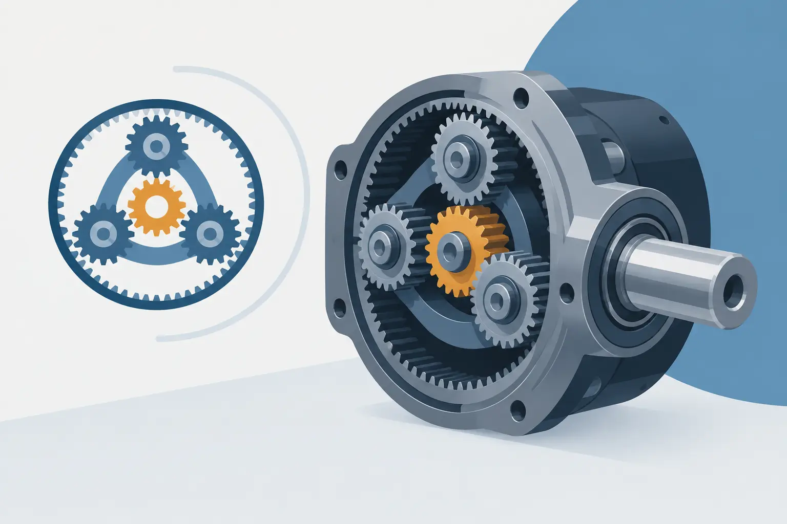
A planetary gearbox can have correct tooth counts, ratio and centre distances yet still fail as an assembly because the carrier was treated as a simple plate. Planetary carrier design is where gear forces become pin loads, bearing reactions, housing interfaces and, ultimately, a manufacturable rotating structure. It deserves the same attention as the involute geometry.
Start with the carrier's actual job
The carrier locates every planet gear relative to the sun and ring. It transmits torque through the planet pins, maintains axial alignment, and usually provides the output interface or a reaction connection. Its geometry therefore controls more than packaging. It affects load sharing between planets, bearing life, mesh contact across the face width and the ability to assemble the gearbox without forcing parts into position.
First establish which member is input, output and fixed. A carrier used as the output member sees a different interface problem from one held stationary as a reaction arm. In either case, identify the full torque path: sun to planet, planet to ring, planet to carrier, then carrier to shaft, flange or housing. Decisions stay visible when this path is considered before adding ribs, pockets or mounting features.
The carrier must also preserve the planetary centre radius. Small errors in pin position alter operating centre distance and can introduce backlash variation or tight mesh. With multiple planets, position error is not merely a local issue. It can prevent equal load sharing and leave one planet carrying more than its expected portion of torque.
Choose the planetary carrier architecture early
A single-sided carrier supports each planet on a cantilevered pin. It can be compact, easy to machine and suitable for modest loads or short face widths. The trade-off is pin bending. As gear face width, torque or overhung output load increases, a cantilevered arrangement can allow enough tilt to concentrate load at one edge of the gear teeth or rolling elements.
A double-plate carrier supports pins at both ends. This arrangement greatly improves pin stiffness and controls angular deflection, particularly where wide helical gears or high-ratio compact stages are involved. It adds an assembly constraint: both plates must hold pin centres accurately and remain parallel under clamp load. A carrier that looks symmetrical in CAD can still bind the planet bearings if the plates distort during machining or fastening.
A one-piece bridge carrier may offer the best stiffness-to-mass ratio for demanding applications, while a fabricated or bolted carrier can simplify manufacture and service. There is no universally correct layout. The appropriate architecture depends on torque, face width, planet diameter, allowable axial space, production method and whether planet components need to be replaceable.
Output interfaces are part of the structure
The output feature should not be added after the carrier has been sized. A keyed bore, spline, hollow shaft, flange or bolt circle changes the local load path and can remove material exactly where the carrier needs stiffness. Check the transition from the carrier body to the output interface for torsional stress concentration, especially around sharp internal corners, thin webs and closely spaced fasteners.
If the carrier mounts to an output shaft, define how concentricity is controlled. A close sliding fit, pilot diameter or locating shoulder should establish position. Fasteners should clamp parts together, not perform the locating function by themselves.
Design the planet pins and bearings as a system
Planet pins are commonly the limiting components in a compact gearbox. They experience bending from gear mesh forces, bearing reactions and, in some layouts, axial loads from helical gearing. A larger pin diameter improves bending stiffness, but consumes space needed for the planet bore, bearing wall thickness and lubricant flow. Increasing pin diameter can therefore force a larger planet gear and alter the entire gearbox envelope.
Select the bearing arrangement with the carrier layout in mind. Needle roller bearings are compact and provide high radial capacity, but often require a hardened, ground pin raceway or an inner ring. Caged needle assemblies can suit higher speeds, while full-complement arrangements can favour load capacity at the cost of speed capability. Small deep-groove ball bearings may simplify assembly but consume more radial space and need suitable control of internal clearance.
For helical planetary stages, the planet bearing system must also manage axial force. A simple radial needle bearing is not enough unless another feature positively locates the planet gear and carries thrust. Thrust washers, flanged bearings or separate axial bearings each bring different friction, speed and lubrication requirements.
Do not size pins only from nominal torque. Include the number of planets, expected load-sharing factor, peak torque, service duty and any external load passing through the carrier. Perfect equal sharing is an assumption, not a production condition. Pin-position tolerance, gear errors, carrier compliance and ring gear distortion all influence the real distribution.
Stiffness protects the gear mesh
A carrier is often assessed by strength first. Stiffness is equally important. If the carrier plates spread, twist or dish under load, the planet gears no longer run on the intended axes. That can reduce effective face contact, raise local tooth stress and shorten bearing life even when calculated material stress remains below yield.
The critical deflections are not limited to the pins. Consider plate bending around each pin bore, torsional twist between the output hub and planet circle, and local deformation near bolt patterns. Thin decorative spokes may look efficient but offer poor torsional continuity. Broad webs with smooth transitions usually provide a more predictable load path.
Material choice changes the balance. Steel can provide a stiff, compact carrier and durable pin bores. Aluminium reduces mass and may be entirely appropriate for lower-duty systems, but generally requires more section thickness and careful attention to bearing seats, thread strength and fretting at interfaces. For prototypes, the manufacturing route also matters. A carrier machined from billet behaves differently from a printed polymer concept or a welded fabrication.
Control geometry, not just dimensions
The planet pin centre locations require positional control relative to the carrier datum and output axis. The pin bores also need their axes controlled for perpendicularity and parallelism, particularly in double-plate carriers. A nominally correct drawing dimension does not guarantee that two opposing bores will accept a common pin without misalignment.
Define functional datums from the interfaces that locate the assembly in service. Typically, this means the output bore or pilot diameter establishes the primary axis, while a machined face establishes axial position. Then locate planet pins from that axis. This approach makes inspection meaningful and avoids a tolerance chain based on non-functional outer surfaces.
Clearance is another system-level decision. The carrier needs room for gear rotation, bearing retainers, lubrication, assembly tools and the ring gear wall. It also needs axial clearance so that planet gears do not rub on carrier plates as components expand or deflect. Too much clearance, however, can make axial location uncontrolled. Use defined thrust faces rather than relying on incidental gaps.
Check assembly before releasing geometry
A planetary carrier is easy to model as an exploded arrangement and surprisingly easy to make impossible to build. Ask practical questions early. Can the planet bearings be installed on the pins? Can retaining rings or fasteners be reached? Does the ring gear need to be fitted before the final carrier plate? Can the assembly pass through the housing bore? Is there a clear route for lubricant to reach each bearing and mesh?
Phasing also needs checking where multiple planets are used. The selected tooth counts and planet positions must permit each planet to mesh correctly with both sun and ring gears. Equal angular spacing is desirable for balance and load sharing, but tooth-count compatibility governs whether it is possible.
This is where a mechanism-specific workflow saves time. GearSuite can configure planetary geometry alongside shafts, bearings and housing interfaces, allowing the carrier, gears and surrounding assembly to be inspected before exporting manufacturable solids. The useful result is not simply a carrier model. It is evidence that the carrier belongs in the mechanism.
A practical validation sequence
Before committing a carrier to manufacture, validate four connected conditions: gear compatibility and phasing, pin and bearing capacity, carrier stiffness, and assembly clearances. Then revisit them after changing any major parameter. A larger output bore, for example, may weaken the hub; a wider gear may require a stiffer double-plate layout; a different bearing may alter the planet pin diameter.
Use the intended manufacturing process to set realistic tolerances and surface requirements. Reamed pin bores, ground pins, controlled bearing seats and a defined assembly method are often more valuable than adding material after a problem appears. For production work, include inspection access in the design so critical centre distances and pin positions can be verified.
A well-designed carrier makes the gearbox behave like the calculation promised. It keeps the planets where the tooth system expects them, carries torque through controlled interfaces and gives manufacturing a part that can be built and checked with confidence. Start there, and the rest of the planetary stage has a far better chance of running quietly, sharing load properly and surviving its intended duty.