
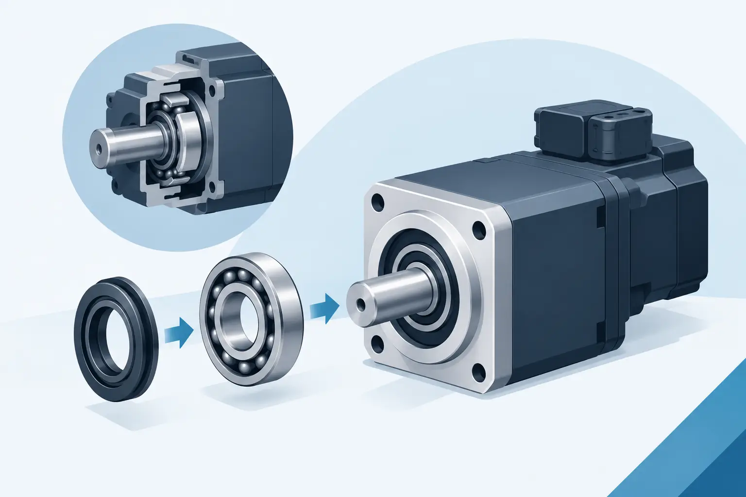
A bearing can be correctly sized on paper and still fail in the assembly. The usual cause is not the catalogue load rating. It is the interface around it: a shaft shoulder that does not locate the ring, a housing bore that distorts during fastening, insufficient clearance for a seal, or a gear load applied too far from the support. This bearing integration guide focuses on the decisions that turn a selected bearing into usable assembly geometry.
For compact gear drives, bearings are not secondary hardware. They establish shaft position, control gear mesh under load and define much of the housing architecture. Treat them as fixed inputs only after the loads, support arrangement and manufacturing route are visible.
Start with the load path, not the bearing code
A bearing choice begins with where forces enter the shaft and where those forces leave it. A spur gear produces radial force and a smaller tangential force that transmits torque. A helical gear adds axial force. A planetary stage distributes force through several planets, but it also introduces carrier stiffness, pin support and alignment questions. Rack-and-pinion systems may impose reversing radial loads and external moments on the pinion shaft.
Map the load path before selecting the bearing arrangement. Mark the gear force position, coupling or pulley position, bearing centres, shaft shoulders and housing walls. A layout that places a gear between two bearings usually limits shaft deflection better than an overhung gear. It may require a wider housing, however, and can complicate assembly. An overhung gear can be appropriate where access or package length matters, but it demands a stiffer shaft and a realistic check of bearing reaction loads.
Do not use torque alone as the design load. Gear tooth forces vary with pitch diameter, pressure angle, helix angle and duty cycle. Include external belt or chain loads, preload, shock loading and any moment created by a coupling that is not perfectly aligned. For mechanisms that reverse frequently, consider the effect of changing load direction on ring creep and on the bearing location strategy.
Fixed and floating support arrangements
Most shafts need one bearing position to locate the shaft axially and another to accommodate thermal growth. This is the fixed-floating arrangement. The fixed bearing, or bearing set, controls axial position in both directions. The floating bearing permits one ring to move axially in its seat, preventing thermal expansion from becoming unwanted preload.
This is not mandatory for every compact unit. A short shaft in an aluminium housing may see very little temperature difference, while paired angular-contact bearings may need deliberate preload for stiffness. Even then, the question remains: where does expansion go? A design that traps both rings at both bearings can work only when the thermal and tolerance stack is understood.
Bearing integration guide: define the interfaces
Once the arrangement is credible, create the shaft and housing features around the bearing rather than treating the bearing as a cylinder dropped into an existing model. The inner and outer ring require reliable radial support and positive axial location where applicable.
A shaft seat needs a controlled diameter, adequate surface finish and enough engagement length to support the full ring width. The shaft shoulder must be high enough to locate the inner ring without contacting the cage, seal or chamfer. The same rule applies to the housing shoulder and outer ring. Use the bearing manufacturer's abutment dimensions, not a visual estimate from the nominal bearing size.
Provide a release feature at the base of a shaft shoulder. A fillet that is too large prevents the bearing from seating; an abrupt corner creates a stress concentration. A small relief groove or correctly limited fillet gives the ring face a clean locating surface. In compact assemblies, this detail is easy to omit because it is almost invisible in a general CAD view. It matters at manufacture and assembly.
The housing bore also needs a plan for retention. A shoulder and cover plate are often simpler and more serviceable than relying on adhesive. Circlips save axial space but introduce groove geometry, local stress and a reduced support face. Threaded retainers can be effective where access exists, but they add components and assembly time. Select the method based on axial load, service requirements and production process rather than package size alone.
Fits are a load-direction decision
Interference and clearance fits are not generic preferences. Choose them according to which ring rotates relative to the applied load. A ring subjected to a rotating load generally needs an interference fit to prevent creep. A ring under a stationary load may use a looser fit where axial movement or easier service is needed.
For example, a rotating shaft with a stationary housing commonly calls for an interference fit on the inner ring. The outer ring may be a transition or clearance fit if it serves as the floating element. But an outer ring can also experience a rotating load depending on the mechanism and load direction. Review the load in the ring's frame of reference, not merely whether the shaft turns.
Material changes the result. An aluminium housing expands more than a steel bearing outer ring as temperature rises and may lose interference. Thin-walled housings can also deform as the bearing is pressed in or when cover bolts are tightened. If the housing is printed, cast or machined from a softer alloy, validate the bore stiffness and long-term retention rather than copying a fit intended for a thick steel gearbox casing.
Control stack-up before defining tolerances
Bearing seats set the effective position of gears. Their tolerances therefore influence backlash, contact pattern, preload and coupling alignment. A good integration model shows the complete axial stack: shaft shoulder, bearing ring, spacer, gear hub, retaining feature, cover and any shim. If two components are both intended to locate the same ring face, one may become an unintended clamp point.
Preloaded angular-contact bearings require particular discipline. The preload is affected by bearing arrangement, spacer length, shoulder squareness, housing deflection and temperature. A nominal spacer dimension does not guarantee a usable preload once manufacturing variation is included. Where stiffness is critical, ground spacers, selective shims or a defined adjustment procedure may be justified. For low-cost drives, a deep-groove ball bearing arrangement may be more tolerant, at the cost of lower axial stiffness.
Radial run-out and face run-out deserve the same attention. A gear mounted against a poorly controlled shaft shoulder can wobble even when the bearing itself is high quality. That error appears as mesh variation, noise and local tooth loading. Define datum features from the bearing seats outward so the shaft, gear and motor interface share an intelligible reference scheme.
Build for assembly, inspection and service
A press fit needs a pressing route. Before releasing geometry, ask which ring receives the press force and whether the tool can reach it. Pressing through the wrong ring transfers force through rolling elements and can damage the bearing before first use. If a bearing is installed into a housing and then onto a shaft, the assembly sequence must still provide access to the relevant ring faces.
Allow clearance for tools, circlip pliers, retaining screws and pullers. Keep seal lips away from sharp assembly edges. Add lead-in chamfers to shaft seats and housing bores, while ensuring they do not reduce the usable seating length. These are small features, but they determine whether an operator can assemble the drive repeatably without improvised methods.
Lubrication must also have a physical route. Greased-for-life bearings may need separation from gearbox oil, while open bearings may be appropriate where the housing oil system supplies them. Seals increase contamination protection but add friction and heat. There is no universal answer: operating speed, environment, orientation and planned service interval decide the balance.
Inspect the assembly in section and in exploded view before export. Check that shoulder faces contact only the intended ring, that covers do not touch seals, that gear hubs clear bearing shields, and that fasteners do not break into bearing seats. In GearSuite, bearing-fit guidance and live assembly inspection help expose these conflicts while shaft, housing and gear geometry remain parameter-driven.
Validate the mechanism, then release production geometry
The final check is not simply whether components occupy different volumes. Confirm that the shaft has adequate stiffness, bearing reactions are plausible, axial retention matches the load direction and the housing can be machined or produced to the required bore geometry. For high-speed drives, add thermal behaviour and balance to the review. For slow, high-torque reducers, focus on housing deflection, static capacity and the effects of shock loads.
Export only when the mechanism remains coherent as an assembly: tooth geometry, centre distance, shaft seats, bearing shoulders, covers and motor interface must agree. A correct STEP file of an incorrect stack-up is still an expensive mistake.
Good bearing integration is visible in the finished machine: gears stay aligned, shafts turn freely, assembly is repeatable and the housing performs the locating work it was designed to do. Make those conditions part of the geometry from the first layout.