
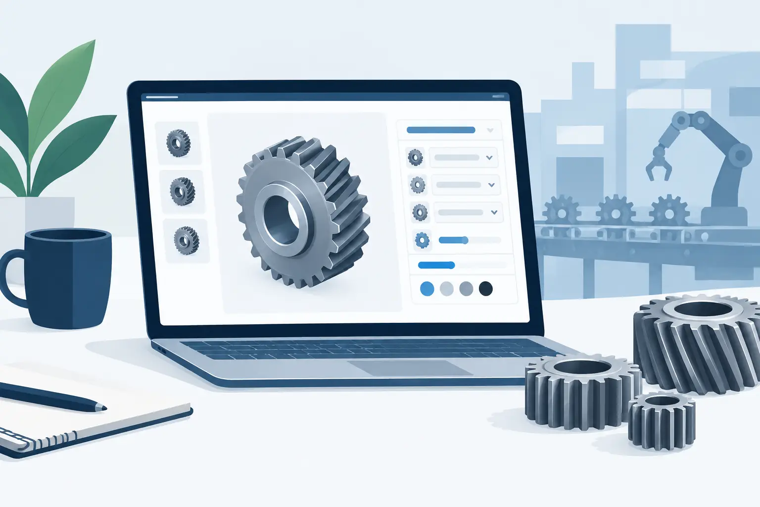
A gear pair can look convincing long before it is usable. The ratio may be right, the teeth may appear to mesh in a viewport, and yet the shaft will not suit the bearing, the housing has no clearance, or the exported part is only a visual approximation. This gear configurator review examines what a serious browser-based tool should provide when the aim is a buildable mechanism rather than a neat render.
The useful question is not whether a configurator can generate a gear. Most can. The question is whether it keeps the design decisions connected: tooth system, centre distance, shaft geometry, bearing interfaces, housing space, motor connection and production-file handoff. That is where a specialist transmission workflow earns its place beside, rather than beneath, general-purpose CAD.
What a gear configurator must prove
A credible configurator begins with the geometry that makes the mechanism work. For spur and helical pairs, this means true involute tooth profiles, appropriate module or diametral convention, pressure angle, tooth count, helix angle where relevant, and a centre distance derived from the selected system. A simplified tooth shape may be suitable for a demonstration model. It is not sufficient for a part expected to transmit motion, load or torque.
The same standard applies beyond a single mesh. A planetary gearbox needs the sun, planet and ring relationship to remain coherent. A cycloidal reducer needs its disc, pin arrangement and eccentric motion to be considered as a mechanism. Rack-and-pinion work needs the rack, pinion and linear travel to be treated as linked geometry. A tool that produces isolated bodies leaves the coordination problem with the user.
This distinction matters most when the concept begins to acquire real constraints. A 3:1 reduction is easy to state. Selecting the tooth numbers that achieve it while preserving a practical centre distance, avoiding undercut risk, fitting bearings and maintaining a compact housing is the engineering work.
Geometry should stay parametric
Parameters should drive the model rather than merely annotate it. Change the module, tooth count or face width and the mating components should respond in a visible, predictable way. The value is not just speed. It is traceability. When a prototype needs a larger bore, a different bearing series or a revised motor interface, the designer should be able to see what that decision changes before exporting anything.
Useful detail by default means displaying the dimensions that affect manufacture and assembly. Pitch diameters, outside diameters, bore sizes, shaft shoulders and housing clearances should not be hidden behind a vague statement that the design is ‘optimised’.
Configure the mechanism, not just the gears
The strongest configurators treat gears as part of an assembly. A practical workflow moves from transmission requirements to components that can actually be mounted. Start with the ratio, expected arrangement and space available. Then establish the tooth system and gear dimensions. From there, shafts, bearings, support features, housings and input interfaces need to develop around the selected geometry.
This is where a focused platform such as GearSuite differs from a plain gear calculator. The goal is not a table of calculated values or a loose STL of a cog. It is assembly geometry that can be inspected as a compact power-transmission system.
For makers and prototype teams, guided choices are particularly useful when they are explicit. Bearing-fit guidance, for example, should point towards compatible diameters and shoulders without pretending that a generic selection has solved every loading, lubrication or tolerance decision. The tool can reduce avoidable mistakes. It cannot replace a duty-cycle calculation for a heavily loaded machine.
There is also a clear advantage over constructing standard mechanisms from scratch in CAD. Modelling a single custom gear is manageable for an experienced designer. Rebuilding a gearbox whenever tooth count, reduction ratio or shaft arrangement changes is slow and vulnerable to missed updates. A configurator is most valuable when it removes repetitive construction while leaving the key engineering decisions visible.
Inspect before committing to manufacture
A review of any gear configurator should pay close attention to inspection. A 3D view is useful, but a static assembled image is not enough. The designer needs to understand how parts occupy space, where components meet and whether the mechanism can be assembled in the intended order.
Exploded views help expose the relationships that are easy to miss in a crowded gearbox: bearing positions, shaft direction, fastener access, gear placement and the boundary between rotating and fixed parts. They are especially valuable for small teams, where the person configuring the mechanism may also be preparing drawings, printing a prototype or discussing the build with a machine shop.
Visual feedback should not be mistaken for validation, however. A model can be visually clean while being mechanically unsuitable. Inspection tells you what is present. Engineering checks tell you whether selected relationships are feasible.
Decisions stay visible
The interface should make incompatible choices obvious at the point they occur. If a selected shaft diameter conflicts with a bearing bore, if a planetary tooth combination will not satisfy the required relationship, or if geometry collides with a housing feature, the response should be direct. Late warnings are costly because they arrive after the designer has already built expectations around a concept.
The ideal behaviour is neither a black box nor an unhelpful refusal. A useful configurator identifies the failed condition and preserves the parameters that caused it, so the user can decide what to change. Perhaps the target ratio is fixed but the package diameter can grow. Perhaps the bearing is fixed by stock availability but the shaft should change. Engineering is often a controlled trade-off, not a single correct answer.
Validate the limits that matter
A specialist configurator can perform meaningful checks, but the scope must be understood. Geometric and arrangement validation is highly valuable: meshing relationships, centre distances, interference, component compatibility and basic fit guidance can all be assessed early. This prevents a large class of avoidable redesign work.
It does not automatically certify the mechanism for every operating condition. Material selection, heat treatment, tooth strength, fatigue life, lubrication, noise, thermal behaviour, manufacturing process and application-specific safety requirements depend on details beyond a general configuration workflow. A printed low-load demonstrator, a CNC-machined fixture drive and a commercial actuator gearbox do not carry the same design obligations.
That is not a weakness if the boundary is clear. A browser-based tool should accelerate the transition from idea to manufacturable geometry, then hand off cleanly to the calculations, drawings and review procedures appropriate to the application. Engineering, not a toy, means being honest about both the checks provided and the checks still required.
Export quality is part of the review
Export is where a configurator either saves time or creates a second modelling job. STL is useful for quick additive prototypes and visual checks. STEP is generally the more useful choice for production-oriented CAD handoff because it carries solid geometry into downstream workflows. DXF may be appropriate for flat profiles, laser-cut parts or documentation needs.
The important point is that exported files must reflect the configured mechanism. A file that requires the user to rebuild bores, faces, housings or mating features has not completed the job. Manufacturing-oriented output should preserve the parts needed for the selected workflow, whether that is a test print, a machinist’s review or integration into a wider assembly.
Export permissions also deserve scrutiny. A freemium model can make sense when it allows users to explore the workflow before committing, while paid access supports complete mechanisms, project storage and wider STEP capacity. Occasional users may prefer one-off export credits; teams iterating on several designs usually need a subscription. The practical test is transparency. Users should know what can be configured, saved and exported at each level before they invest time in a design.
Where a focused configurator has limits
A mechanism-specific tool is not intended to replace every CAD or simulation environment. If the project requires a highly irregular casting, a complex machine frame, bespoke sheet-metal guards or extensive finite-element analysis, another tool will remain part of the process. That is normal.
The better approach is to use each tool where it is strongest. Configure and validate the standard transmission architecture in the specialist environment. Export real solids. Then integrate those parts into the larger product assembly, add custom surrounding structure and complete application-specific analysis. This division of work avoids spending hours reproducing established gear relationships by hand.
There are limits within gearing too. A configurator is most effective when the design belongs to the mechanism families it supports. A novel tooth form, an unusual non-circular gear or a transmission with research-level requirements may need custom modelling and specialist analysis. Focus is a benefit when it matches the task, not a promise that every transmission problem has the same answer.
A practical verdict on gear configurator value
The best result from a gear configurator is not a faster way to make a gear-shaped file. It is a shorter, clearer path from ratio and packaging requirements to inspected, validated assembly geometry and usable exports. True involute profiles, linked components, visible constraints and manufacturable solids are the criteria that separate an engineering workflow from a visual generator.
For a maker testing a compact drive or an engineering team developing a repeatable mechanism, the return is usually measured in iterations avoided. Start with the parameters that cannot move, expose the constraints early, and export only once the assembly makes physical sense. Make the idea mesh before asking the workshop to make it real.