
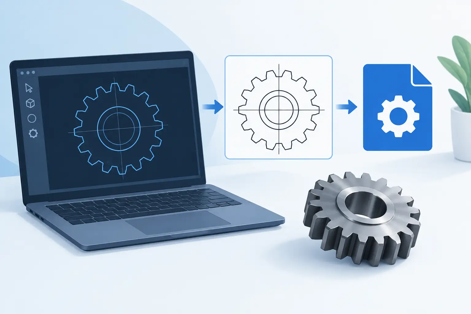
A DXF gear profile generator should not merely draw a convincing toothed circle. It should create geometry that mates correctly, fits the intended shaft and bearing arrangement, and survives the manufacturing process chosen for the part. For a laser-cut prototype, CNC-machined gear, or waterjet-cut mechanism plate, the difference is not cosmetic. A small error in tooth form, centre distance or bore detail becomes noise, binding, backlash or a part that cannot be assembled.
DXF is a useful hand-off format because it carries clean 2D geometry into CAM, laser, waterjet and profile-cutting workflows. It is not, however, an engineering decision by itself. The real work happens before export: defining a compatible tooth system, setting the operating geometry and deciding whether the resulting gear is suitable for the load, material and process.
What a DXF gear profile generator must produce
For standard external spur gears, the tooth flanks should follow a true involute profile. This is the geometry that preserves a consistent pressure angle as the gears rotate, allowing smooth motion when the gears are made to the same system and installed at the correct centre distance. A circular approximation or decorative tooth shape can look acceptable on screen while producing poor contact in a physical assembly.
A useful generator starts with the values that define the gear rather than asking you to sketch teeth manually. In metric work, that normally means module, tooth count and pressure angle. The module sets tooth size; tooth count sets pitch diameter and ratio; pressure angle determines the tooth system. A 20-degree pressure angle is common, but common is not the same as universal. Match the existing mating gear when replacing a part.
The profile also needs the root, tip and transitions to be calculated as working geometry, not as an afterthought. Root clearance matters. So does the bore, hub region, keyway or fastening pattern. If a profile cutter only receives an outside diameter and an approximate tooth count, it cannot establish whether the teeth will mesh as intended.
Start with the mating pair, not one gear
A gear is defined by its relationship with another gear. The simplest trap is generating a pinion and driven gear separately, then assuming matching module is enough. It is a necessary condition, but the pair must also share the same pressure angle and be assembled at the appropriate centre distance.
For a standard spur pair, the nominal pitch diameters are calculated from module and tooth count:
`pitch diameter = module × number of teeth`
The nominal centre distance is half the sum of those pitch diameters. That equation is simple, but it is the first dimensional check worth making before you export anything. If a housing fixes the shaft spacing, choose tooth counts and module that work with that constraint. Do not scale a DXF after generation to make it fit. Scaling changes the module and invalidates the tooth system.
The pinion deserves particular attention. Low tooth counts can introduce undercut at the root, reducing tooth strength and altering the contact conditions. Depending on the pressure angle, profile shift and application, a small pinion may still be valid, but it should be a deliberate choice supported by geometry checks. A generator that flags an infeasible or marginal configuration saves time before material is cut.
Ratio is only one requirement
A 3:1 ratio can be achieved with many tooth-count combinations. A 12-tooth pinion with a 36-tooth gear is compact, but may be a poor choice for a highly loaded arrangement. A 20-tooth pinion with a 60-tooth gear occupies more space yet usually offers less risk at the pinion root. Packaging, torque, speed, material and process decide which compromise is appropriate.
This is why generic ratio calculators are not enough. They answer one arithmetic question. A useful design workflow keeps ratio, tooth geometry, shaft spacing and part dimensions visible together.
Configure the production geometry
Once the tooth pair is correct, configure the details that turn a theoretical gear into a part. The bore is not simply a hole placed in the middle. Its diameter must leave enough material at the hub and web, and it must correspond to the shaft interface. A close running fit, a press fit, a keyed shaft and a clamp hub each need different geometry and tolerances.
For a profile-cut gear, think about the complete 2D contour. Include the bore, mounting holes, lightening features and any internal profile required by the assembly. Keep sufficient material around small holes and avoid narrow internal corners that the chosen tool or kerf cannot reproduce. If the part will be machined, cutter radius compensation and minimum tool diameter matter. If it will be laser cut, kerf, heat-affected edges and material thickness matter.
DXF describes nominal geometry. Manufacturing compensation usually belongs in the CAM or cutting workflow, unless your process has a proven, controlled allowance strategy. Applying kerf compensation twice is a common way to create an undersized bore or an oversized external gear. Agree where compensation happens before releasing the file.
Spur, helical and the limits of a 2D file
A DXF profile is most direct for spur gears because the tooth form is constant through thickness. Helical gears require a three-dimensional tooth surface and a helix angle, so a top-view DXF alone cannot define the finished gear. It may still help as a reference or for a related plate feature, but it is not a substitute for a STEP model or a manufacturing strategy that accounts for the helix.
The same distinction applies to mechanisms. A DXF can be ideal for a laser-cut spur gear or a rack outline. It is not sufficient evidence that shafts, bearings, spacers, housings and fasteners will coexist. Use the 2D export where it fits, while keeping the assembly model available for spatial decisions.
Inspect before exporting the DXF gear profile
Inspection should be quick and visual, but not superficial. Check the tooth count and direction of rotation first, then look at the pair in mesh. Confirm the centre distance, outside diameters, bore dimensions and clearance around the hub. If the mechanism has a housing, check that the gear envelope clears walls, fasteners and neighbouring components through the required motion.
Backlash is another decision that should stay visible. A no-backlash nominal model can be useful for checking the theoretical pair, but real assemblies need allowance for manufacturing variation, lubrication, thermal movement and application requirements. The right amount depends on gear size, material, accuracy grade and duty. A lightweight acrylic prototype and a metal reduction stage under sustained load should not be treated alike.
For compact drives, inspect the shaft and bearing arrangement at the same time. A gear that meshes perfectly can still create an impractical design if its hub collides with a bearing, if the shaft shoulder has nowhere to sit, or if the housing leaves no room for assembly. Mechanism-specific tools such as GearSuite are useful here because tooth profiles, shafts, bearings and assembly geometry are considered within one configured design rather than as disconnected sketches.
Export a file the workshop can use
Before sending a DXF to production, confirm its units. Millimetres are common in UK and EU mechanical work, but DXF files can be interpreted differently by downstream software. State the intended unit in the drawing package or job notes and verify it by measuring a known feature after import.
Keep the export clean. A profile-cutting file should contain the intended outlines without duplicate entities, construction circles, hidden reference geometry or overlapping segments. Confirm that internal and external contours are closed where the process requires closed loops. If holes, bores and teeth are placed on separate layers, use clear names that help the CAM operator distinguish features rather than guess at design intent.
Do not treat the exported file as final until it has been opened in the receiving software. Measure the pitch diameter, bore and outside diameter. Zoom into a tooth root to check for broken splines, unexpected arcs or geometry simplification. This takes minutes and can prevent a full sheet of rejected parts.
Choose the generator by the decisions it exposes
The best DXF gear profile generator is not necessarily the one with the most settings. It is the one that makes the relevant settings explicit and helps you identify invalid combinations early. For a simple replacement gear, that may mean module, pressure angle, tooth count, bore and centre distance. For a compact gearbox, it should extend to shafts, bearing seats, housing space and exportable manufacturing geometry.
Use a fast 2D export when the process genuinely needs a 2D contour. Use a complete mechanism model when the risk sits in the interfaces around the gear. Built for real parts means keeping those decisions connected until the cutter starts.