
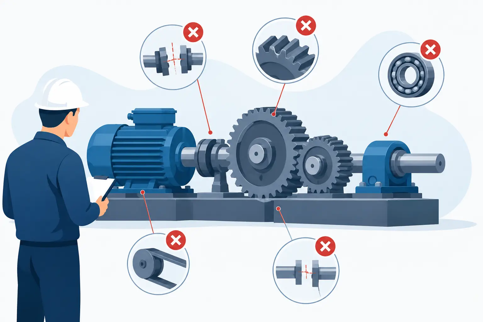
A gearbox can show the correct ratio, fit inside the envelope and still fail as soon as it sees a real load. That is the problem with many power transmission design mistakes: the error is rarely isolated to one gear or one shaft. It appears in the relationship between tooth geometry, bearing positions, housing stiffness, motor torque and manufacturing method.
The useful question is not whether each part can be drawn. It is whether the complete assembly can transmit the required motion for the required life. Decisions stay visible when the mechanism is treated as an assembly from the first layout.
1. Designing for ratio before designing for load
A target reduction ratio is usually the first requirement, but it is not the design case. Torque, duty cycle, starts per hour, shock loading, direction reversals and allowable backlash determine whether a chosen gearset is sensible.
A small pinion may achieve the required ratio neatly, especially in a compact planetary layout. But high torque at the pinion can push tooth-root stress, contact stress and shaft deflection beyond acceptable limits. The issue is often worse when a motor's nominal torque is used without considering stall torque, acceleration peaks or reflected inertia.
Start with the load path. Establish continuous torque, peak torque, speed range and service conditions before selecting module, face width or stage ratio. For intermittent hand-operated equipment, a compact solution may be entirely reasonable. For a machine that cycles all day, the same geometry may need a larger module, wider face or an additional reduction stage.
2. Treating tooth count as a ratio-only decision
Tooth count controls more than ratio. It affects undercut, contact ratio, sliding velocity, pinion strength, centre distance and whether a standard tooth system can be manufactured without correction.
A low-tooth pinion is particularly tempting when space is limited. With standard full-depth involute teeth, however, it can introduce undercut and weaken the tooth root. Profile shift can help, but it changes working geometry and needs to be considered with the mating gear, centre distance and backlash as a complete system.
Helical gears add another trade-off. Their overlap can improve load sharing and running smoothness, yet the helix angle creates axial thrust. That force must be reacted by suitable bearings and retained by the housing. Selecting helical gears for quietness while treating the bearing arrangement as an afterthought simply moves the problem downstream.
Use true involute geometry rather than a visual approximation. A gear that looks correct in a viewport is not necessarily compatible with its mating part, its specified centre distance or the chosen manufacturing process.
3. Ignoring shaft deflection and bearing spacing
Gears do not operate on perfectly rigid shafts. A shaft bends under radial gear force, and a helical gear also applies axial force. Even modest deflection can change contact across the face width, concentrate load at one edge and increase noise, wear and tooth stress.
A common layout mistake is placing a gear far from its nearest bearing to simplify assembly or clear another component. The overhung load creates a bending moment that the shaft and bearing set must carry. Increasing shaft diameter helps, but may conflict with bearing bores, gear hubs and packaging.
Bearing spacing matters just as much. Bearings set too close together may leave the shaft poorly supported around a loaded gear. Bearings spaced widely can improve stiffness, but may lengthen the housing and complicate assembly. There is no universal best arrangement. The right choice depends on gear position, load direction, bearing type, shaft shoulders and the available housing structure.
Inspect the full shaft stack: gear hub, spacers, bearing seats, retaining features and clearances for assembly tools. If those details only appear after the gears are selected, the design is already being forced into compromises.
4. Assuming a bearing bore is a shaft design
A bearing bore is one constraint, not a complete shaft specification. The shaft needs correctly located seats, shoulders, radii, retention and transitions that can actually be machined. A sharp shoulder may locate a bearing in CAD but create a stress concentration or clash with the bearing chamfer in the real part.
Fits must also suit the loading condition. A rotating inner ring under radial load generally requires an interference fit to prevent creep, while a stationary ring may use a different fit depending on load and service requirements. Thermal expansion, aluminium housings and frequent disassembly can change the sensible choice.
Do not overlook axial location. A pair of bearings needs a defined strategy for thrust and thermal growth. Over-constraining both ends of a shaft can preload bearings as temperature changes. Leaving both ends effectively floating can allow unwanted axial movement. One locating bearing arrangement and one floating arrangement is often appropriate, but the correct approach depends on bearing type and operating temperature.
5. Designing a housing as an empty box
The housing is part of the transmission. It establishes centre distance, supports bearing outer rings, controls alignment and provides the structural loop that reacts gear forces. Thin walls or unsupported bearing bores can flex enough to alter mesh under load.
This matters in printed prototypes as well as machined or cast production parts. A printed enclosure may be useful for checking packaging and motion, but its material stiffness, layer orientation and heat resistance can make it unsuitable for validating long-term gear contact. Treat prototype evidence honestly: a mechanism that turns freely on the bench has not necessarily passed a load test.
Provide enough material around bearing seats, sensible ribs where loads enter the housing, and access for fasteners and assembly. Split lines need attention too. If a housing split passes through a bearing seat without reliable location features, alignment can change every time the assembly is opened.
6. Leaving backlash and tolerance until the end
Backlash is not an embarrassment to be eliminated at all costs. It is necessary clearance in many gear systems, allowing for tooth thickness variation, centre-distance tolerance, housing movement, lubrication and thermal effects. The required amount depends on size, accuracy grade, operating temperature and application behaviour.
Too little backlash can cause binding as parts warm up or as a housing distorts under load. Too much can create positioning error, impact during reversals and audible rattle. Rack-and-pinion systems are especially sensitive because backlash often appears directly as lost linear motion.
Manufacturing method changes the calculation. Machined gears, moulded polymer gears, sintered parts and printed prototypes each have different tooth accuracy and surface characteristics. A nominally correct mesh should therefore be checked against the tolerances that the selected process can hold, not an ideal CAD dimension.
Useful detail by default means viewing the assembled mesh, not only exporting individual solids. Check centre distance, tooth engagement, backlash allowance, bearing alignment and clearance through a rotation. A mechanism-specific workflow such as GearSuite makes those relationships easier to inspect before production geometry is released.
7. Treating lubrication and heat as maintenance issues
Lubrication is a design input. It affects wear, efficiency, temperature, seal selection and acceptable speed. Grease may suit a sealed, low-speed compact gearbox, but can churn and heat at higher speeds. Oil can improve cooling and high-speed lubrication, yet requires attention to sealing, orientation, fill level and splash paths.
Losses accumulate across stages. Tooth friction, bearing drag, seal drag and lubricant churning all become heat inside a small housing. If the housing cannot reject that heat, viscosity falls and clearances change. Polymer components may soften; grease may migrate away from the contact zone.
Specify the intended operating orientation and ambient conditions. A reducer mounted vertically may not distribute lubricant as it does when mounted horizontally. If the equipment operates near a heat source, in dust or in washdown conditions, those constraints belong in the first design review, not in a later maintenance note.
Build the assembly before committing to parts
The fastest way to create expensive rework is to validate gears, shafts, bearings and housing features in separate mental compartments. Configure the mechanism, inspect the assembly geometry, validate engineering constraints, then export manufacturable solids. That sequence exposes the compromises while they are still cheap to change.
A transmission that survives production is not the one with the most ambitious ratio or the smallest package. It is the one whose tooth geometry, support structure, tolerances and operating conditions agree with each other.