
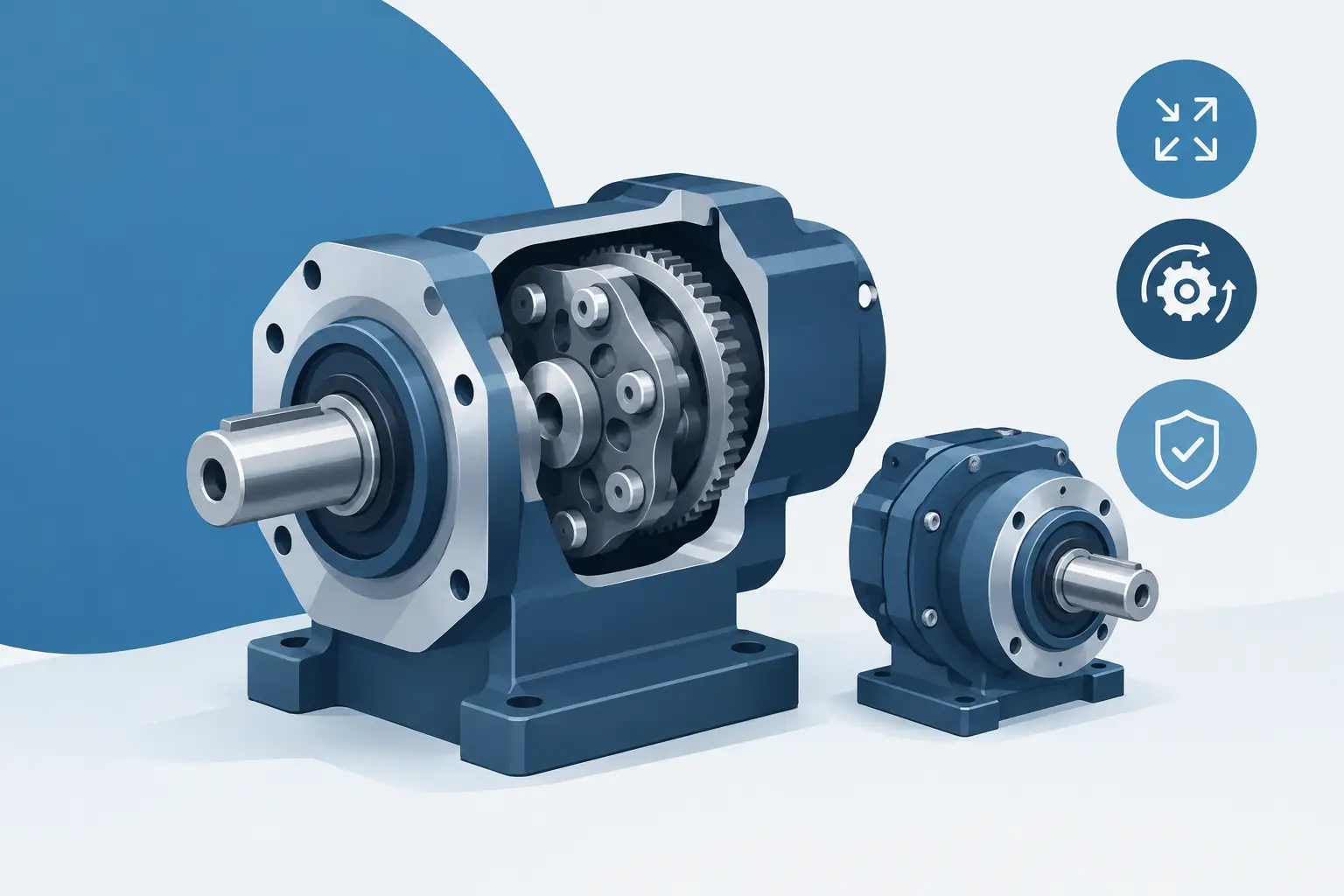
A compact drive can fail long before the motor reaches its rated torque. The usual causes are not the ratio on paper. They are pin contact, disc clearance, bearing support, eccentric loading and a housing that cannot hold the mechanism’s geometry. Cycloidal reducers address the need for high reduction in a small envelope, but they reward disciplined assembly design.
Unlike a conventional spur gearbox, a cycloidal stage does not rely on one or two tooth pairs carrying the load. A lobed disc rolls against an array of housing pins, with several contacts sharing torque at once. This gives cycloidal reducers their appeal in compact machinery: high ratios, good shock tolerance and a coaxial output arrangement. It also makes the details non-negotiable.
How cycloidal reducers create reduction
A basic cycloidal reducer contains an eccentric input, one or more cycloidal discs, a fixed ring of pins or rollers, and output pins connected to an output flange. As the eccentric rotates, it drives the disc around the stationary pin ring. The disc has one fewer lobe than the number of ring pins.
That difference of one creates the reduction. If the housing has 41 pins and the disc has 40 lobes, one full input revolution moves the disc by only one pin pitch relative to the housing. The reduction is approximately 41:1 for a single-stage arrangement, depending on the selected output reference and configuration.
The output does not usually follow the disc directly. Output pins pass through clearance holes in the disc and collect its slow orbital motion. This arrangement keeps the output shaft on the centreline even though the input eccentric is offset. It is a useful architecture where motor, reducer and driven shaft must remain coaxial.
The apparent simplicity can be misleading. The disc profile is not a decorative wave. It must be generated around the ring-pin geometry, eccentricity and intended clearance. A profile that looks plausible in a sketch may bind, lose contact quality or develop impractical thin sections when made into a real part.
Why the contact pattern matters
The central advantage of a cycloidal mechanism is distributed contact. Under load, several lobes can engage with the ring pins. Load sharing reduces contact stress compared with a layout where one small gear tooth carries most of the transmitted force.
In practice, the number of contacts carrying meaningful load is lower than the number visible in a CAD view. Manufacturing tolerances, elastic deflection, surface finish and local clearance all affect engagement. Designing on the assumption that every lobe carries an identical share is optimistic. The housing stiffness and pin positioning determine whether the mechanism behaves as intended.
Ring pins can be plain dowels, hardened rollers or purpose-designed rolling elements. Plain pins simplify the housing and can suit lower-speed or lower-duty applications. Rolling pins reduce sliding losses but introduce their own requirements for retention, lubrication and available radial space. Neither choice is automatically better. The right option depends on speed, torque, duty cycle, target efficiency and manufacturing capability.
The output pins deserve the same attention. Their holes in the disc require enough clearance for orbital movement, but excessive clearance increases lost motion. If the application demands positional accuracy, backlash must be considered across the complete assembly: eccentric bearings, disc-to-pin contact, output-pin holes, shaft fits and housing bores.
Design the mechanism as an assembly
A cycloidal reducer is not just a disc and a pin circle. It is an assembly geometry problem. Start with the required ratio, motor speed and output torque, then set the package diameter and axial length available. These constraints influence the pin count, disc diameter, eccentricity and the size of bearings that can physically support the input.
Set the ratio before choosing the envelope
Higher ratios generally require more ring pins and lobes. That can improve the reduction available in one stage, but it also creates finer features and tighter pitch spacing. For a small fabricated or printed prototype, a very high pin count may be harder to produce accurately than a moderate ratio with a second stage elsewhere in the drivetrain.
Do not select the ratio from motor speed alone. Check the output speed under operating load, the motor’s useful torque range and the reflected inertia of the driven equipment. A reducer that gives an attractive nominal output speed may leave the motor running inefficiently or make acceleration poor.
Size the eccentric and its bearings
The eccentric offset creates the disc orbit. More eccentricity increases the motion available to the disc, but it changes the lobe geometry and bearing loads. The eccentric bearing sees repeated radial loading and must fit both the shaft and the disc arrangement. Bearing width, shoulder locations, retention method and assembly order all need space in the axial stack.
For higher loads, twin discs phased 180 degrees apart are often used. Their orbital forces can partially balance, reducing vibration and improving torque capacity. This adds parts and increases axial length, but it is often a sensible trade where smooth running matters.
Treat the housing as a precision component
The ring pins only work as a controlled array if the housing locates them accurately. Pin bores must be concentric with the output axis and held at the intended pitch circle. A flexible cover plate or thin-walled housing can distort under bearing preload or external mounting loads, changing the contact pattern inside the reducer.
Build the housing around machining and assembly access. Consider how pins are inserted, whether they need a shoulder or retaining plate, how bearings are pressed in, and whether the disc can be installed without forcing components past a shaft shoulder. Decisions stay visible when the housing is modelled with the transmission, rather than added after the reducer geometry is complete.
Material, lubrication and manufacturing choices
A prototype can prove kinematics without proving service life. Polymer discs, printed housings and standard steel dowel pins may be appropriate for a low-load demonstrator. They are not automatically suitable for a continuous-duty actuator or a machine axis.
For production work, contact pressure and wear drive material selection. Hardened pins or rollers, a suitably heat-treated disc, controlled surface finish and compatible lubrication can transform the expected life of the mechanism. Lubricant also affects efficiency and temperature. Grease simplifies sealing and can suit intermittent use; oil may be preferred where speed and thermal load are higher.
Manufacturing method affects the geometry you should choose. CNC-machined discs can support controlled profiles and bearing fits. Wire-cut or laser-cut plates may be useful for certain disc forms, although edge quality and thickness constraints need review. Additive manufacturing is valuable for checking clearances, housing layout and assembly sequence, but dimensional variation around pin bores and bearing seats must be accounted for.
A practical workflow is to configure the ratio and pin geometry, inspect the disc orbit in an exploded view, validate clearances and bearing interfaces, then export only when the parts form a credible assembly. GearSuite is built around that sequence: parameter-driven mechanism geometry, direct inspection and production-file handoff for parts that can be made.
Common mistakes that appear late
The most expensive errors tend to be structural rather than mathematical. A disc may clear the pin ring but collide with a retaining plate. Output pins may fit the disc holes yet have no usable method of attachment to the flange. The eccentric may work in the model but leave no shoulder for bearing location.
Watch for these four failure points during design:
- assuming ideal load sharing across every cycloidal lobe;
- omitting clearance for disc orbit, output-pin travel and assembly tolerances;
- using a housing that cannot maintain pin position under load;
- selecting bearings by diameter only, without checking width, load direction and retention.
These checks are especially relevant when the reducer is integrated with a motor flange. Motor pilot dimensions, shaft extension, keyway or clamp arrangement, and fastener access can consume the space assumed available for the input assembly.
Where cycloidal reducers fit best
Cycloidal reducers suit compact, high-torque duties where shock loads, coaxial layout or high single-stage reduction matter. Examples include rotary tables, compact conveyors, robot joints, indexing equipment, valve actuators and specialist machine fixtures. They are less attractive where very low backlash, exceptional speed capability or the lowest possible manufacturing cost is the primary requirement. In those cases, a planetary, harmonic or conventional geared solution may be a better fit.
The useful question is not whether a cycloidal reducer is inherently superior. It is whether its load-sharing contact, ratio range and package layout solve the constraints of the machine in front of you. Model the pins, bearings, shafts and housing together early. That is where a credible reducer begins.