
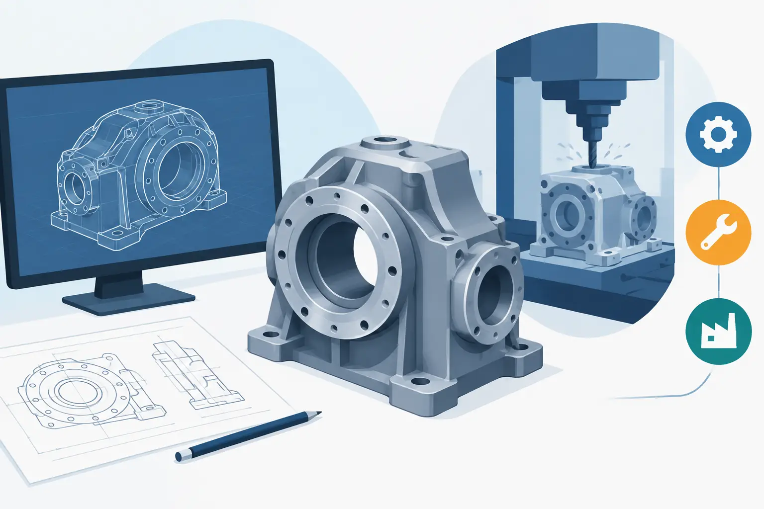
A gear housing is not an enclosure added after the drivetrain works. It is the structure that keeps shafts on centre distance, holds bearing geometry under load, contains lubricant and gives the assembly a practical route to manufacture and service. If you are working out how to design a gear housing, begin with the load path and interfaces, not with an attractive outer shape.
For a small reducer, an error of a few tenths of a millimetre at a bearing seat can change tooth contact, raise noise and shorten bearing life. The housing therefore needs the same engineering attention as the gears themselves. Built for real parts means designing the shell, bores, faces and fixings as one assembly geometry.
Start with the gear mesh and load path
Set the transmission layout before defining housing walls. Confirm the gear type, module or normal module, pressure angle, helix angle where applicable, ratio, centre distance, face width and expected torque. These parameters establish the forces that the housing must react.
A spur pair applies radial and tangential forces at the mesh. A helical pair also introduces axial force, which must be carried through the selected bearing arrangement and into the housing. In a planetary gearbox, the housing may locate a ring gear, support planet pins and close the load loop between carrier and bearings. These are fundamentally different jobs, even when the external package looks similar.
Sketch the force route in plain terms: tooth contact to shaft, shaft to bearing, bearing outer ring to housing bore, housing to mounting face. Every change of direction in that route deserves scrutiny. Thin walls, long unsupported bearing bosses and flexible mounting flanges allow the shafts to move relative to each other. Gear contact then shifts under torque rather than staying where the design calculation assumed.
Establish the bearing arrangement early
Choose bearings before finalising the housing. Bearing outside diameter, width, shoulder requirements, permissible misalignment and axial location all determine bore geometry. A deep-groove ball bearing may suit moderate radial load and a simple locating arrangement. Tapered roller or angular-contact bearings may be necessary where helical thrust, overhung loads or preload control are significant.
Decide which bearing locates the shaft axially and which bearing floats to accommodate thermal expansion. A fully trapped shaft at both ends can generate unwanted axial preload as temperatures rise. The housing needs features that support this decision: shoulders, end covers, spacers, circlips or threaded retainers, with enough tool access to assemble them.
Bearing fits must match the load case. An outer ring subject to a rotating load relative to the housing generally needs an interference fit, while a stationary load may permit a transition or clearance fit. The right tolerance depends on bearing type, housing material, temperature and load. Do not specify a generic press fit without checking the bearing manufacturer’s recommendations.
Define interfaces before wall thickness
The most useful first housing model is often a set of controlled interfaces: bearing bores, shaft seal bores, gear cavity, mounting datum face, motor pilot, bolt pattern and cover split line. Once these are stable, material can be added around them.
This order prevents a common failure: modelling a compact-looking box, then discovering that the bearing shoulders are inaccessible, the motor pilot clashes with a seal carrier or the fixing bolts enter the gear cavity. Decisions stay visible when the functional geometry comes first.
For motor-driven units, define the motor interface as a datum system rather than a collection of holes. The pilot diameter locates the motor. Bolts clamp it. The output shaft and driven machine interface need their own concentricity and face-runout requirements. If the motor pinion runs directly on the motor shaft, the motor pilot-to-bearing relationship becomes particularly important.
Split housings need similar discipline. Place the split line where it supports machining and assembly without weakening the bearing supports. A split passing through a bearing bore can be workable in larger cast gearboxes, but it introduces alignment, sealing and machining demands that may not suit a compact fabricated or machined unit.
How to design a gear housing for stiffness
Wall thickness alone does not create stiffness. Geometry does. A deep bearing boss tied into a broad side wall is usually more stable than a thick but isolated cylindrical boss. Ribs can help, but only when they connect meaningful load paths. Ribs added purely for appearance may complicate machining and create local shrinkage concerns in cast parts.
Work from the bearing centres outwards. Keep the material around each bore sufficiently continuous to resist ovalisation and tilting. Connect the two bearing regions with a stiff web or side plate, especially where the gear mesh applies high separating force. Then examine the mounting arrangement. A housing that is stiff on the bench can distort when clamped to a flexible machine frame through four poorly positioned feet.
There is no universal wall thickness. A small CNC-machined aluminium housing may use a different proportion from a cast iron industrial gearbox or a polymer prototype enclosure. Material modulus, casting process, available machining stock, bolt preload and duty cycle all matter. Use initial rules of thumb only to start the layout, then verify critical deflection with calculation or finite element analysis where load and accuracy justify it.
Do not make the housing excessively rigid at the expense of practical manufacture. Very thick sections increase material cost and machining time. In castings, they can create uneven cooling and defects. In aluminium, they may add weight without improving the bearing-to-bearing stiffness that actually controls mesh alignment.
Build lubrication and sealing into the layout
Gears need a defined lubrication method, not simply an empty volume around them. For splash lubrication, establish the oil level against the lowest rotating gear and check that it provides pickup without excessive churning loss. At higher speed, too much immersion can heat the oil, aerate it and reduce efficiency. At low speed, splash may not reach upper bearings or remote meshes reliably.
Add the practical details while the housing is still easy to change: fill point, level check, drain point at the true low position, breather location and clearance for plugs. A drain plug hidden behind a mounting bracket is a service problem designed into the part.
Seal selection follows shaft speed, shaft finish, pressure, lubricant and contamination exposure. Radial lip seals need a suitable shaft running surface and a lead-in chamfer that does not cut the lip during assembly. Labyrinth features can reduce contamination ingress, but they consume axial space and are not a substitute for a proper sealing strategy where oil retention is required.
Allow for pressure equalisation. A sealed housing that warms up during operation can build internal pressure and push oil past otherwise adequate seals. A breather may be enough for general machinery; washdown, dusty or outdoor equipment may need a more controlled solution.
Choose the manufacturing route before detailing features
A one-off machined housing, a welded fabrication and a die-cast production enclosure should not share the same feature set. Machined billets favour accessible bores, sensible tool radii and fewer deep pockets. Castings benefit from draft, consistent sections and machining pads around precision interfaces. Fabrications need a plan for weld distortion and post-weld machining of bearing bores.
Design datum surfaces that can actually be held during manufacture. Critical bearing bores are often best machined in one setup, or line-bored where the form and scale require it. This controls bore-to-bore centre distance and coaxiality more reliably than tolerancing each feature independently on a drawing.
Use standard fasteners where possible and leave room for sockets, spanners and cover removal. Specify dowel pins if a removable cover must repeatedly return to a precise position. Clamping bolts do not automatically locate a cover accurately, particularly when bearing outer rings are supported across the joint.
Inspect the assembly, not just the shell
Before export, inspect the complete mechanism in section and exploded views. Check gear tip clearance to the housing, shaft-to-wall clearance, bearing shoulder contact, seal access, fastener reach and tool paths. Rotate the assembly mentally and, where available, in the model. The interference that matters may only appear at an assembly angle or when a cover is fitted.
A mechanism-specific workflow such as GearSuite helps keep true involute gear geometry, shafts, bearings and housing interfaces coordinated while the design changes. The value is not a prettier model. It is earlier feedback on whether the intended geometry can become manufacturable solids.
Carry the final dimensions into production documentation with clear datums and tolerances on the features that control function. The gear cavity can often tolerate generous dimensions. Bearing bore position, mounting-face flatness, bore perpendicularity and motor pilot concentricity usually cannot.
A good housing makes the gear pair behave like the calculation says it should. Give the bearing centres a stable home, make lubrication and assembly deliberate, and leave the machinist a realistic way to hold every critical surface.