
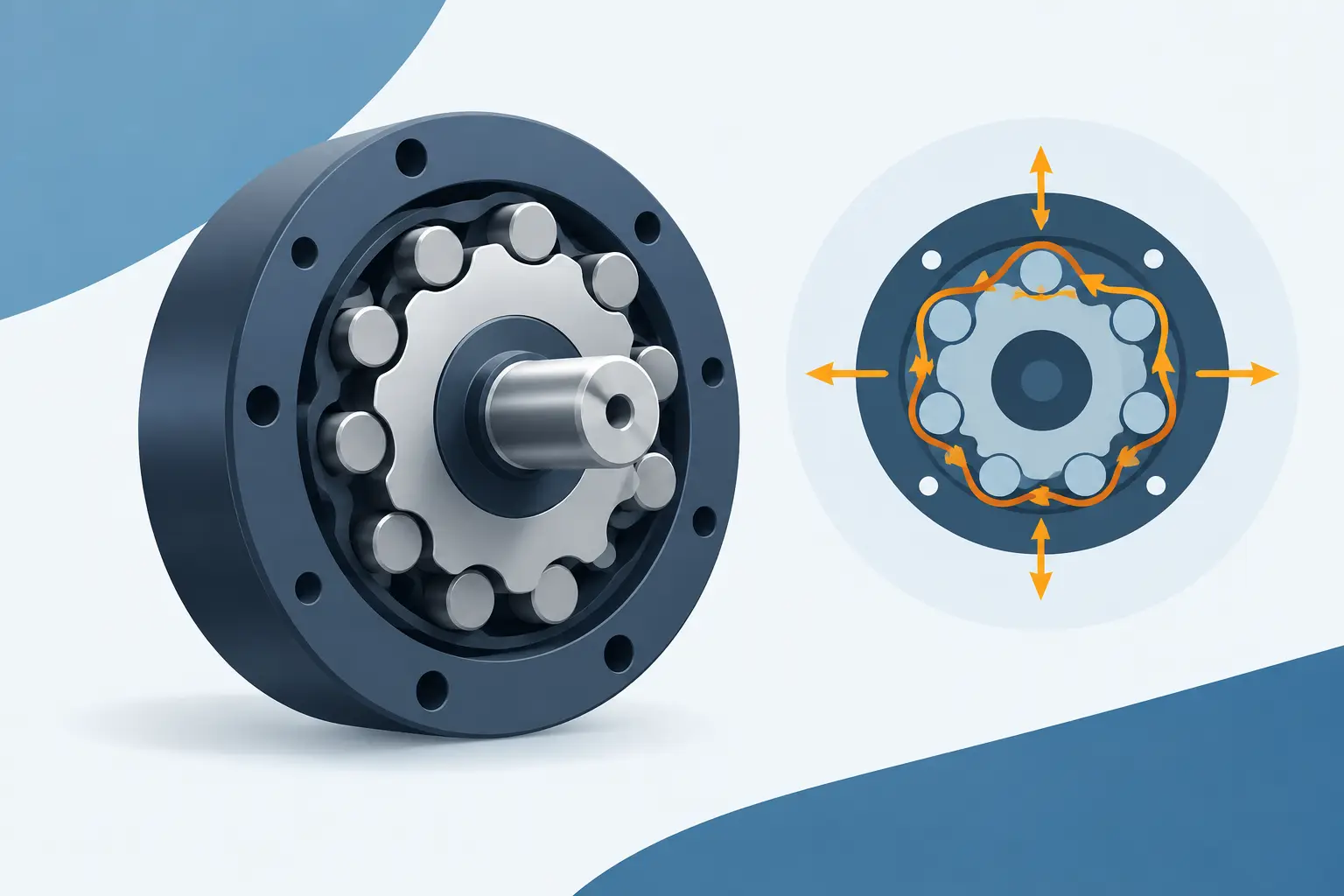
A cycloidal reducer can have the correct ratio, eccentricity and disc profile yet still fail as an assembly because of poorly specified cycloidal output pins. These pins are the load-transfer elements between the cycloidal disc and the output flange. Their geometry determines how torque leaves the disc, how much backlash the mechanism develops, and whether the assembly remains practical to machine and assemble.
The pins are often treated as simple dowels placed on a pitch circle. That is only partly true. In operation, each pin sees repeated contact loading through holes or rollers in the cycloidal disc. The load is shared unevenly, changes with angular position, and is affected by clearance, stiffness and manufacturing error. Built for real parts means designing that interface as a system, not selecting a nominal pin diameter after the disc is finished.
What cycloidal output pins actually do
In a typical single-stage cycloidal reducer, an eccentric bearing drives a lobed disc around a stationary ring of outer pins. The disc rotates slowly relative to the housing. Output pins fixed to the output flange pass through enlarged holes in the disc. As the disc orbits, its motion pushes against those pins and turns the output flange.
The output pins therefore perform two related jobs. They transmit torque from the disc to the output member, and they accommodate the disc's eccentric orbit. The holes in the disc must be larger than the pins, otherwise the disc cannot move through its required path. That necessary clearance is also where backlash, impact and local contact stress begin.
For a reducer with output torque \(T\), output-pin pitch radius \(R_o\), and \(n\) pins carrying load, a first estimate of tangential force per engaged pin is:
\[ F_t \approx \frac{T}{R_o \times n} \]
This is useful for early sizing, but it is not a final stress calculation. Not every pin carries the same load. Clearance means a small number of pins may contact first, particularly under reversing torque. Disc flex, flange stiffness and positional variation can make the effective number of engaged pins much lower than the installed pin count.
Pin count and pitch circle are coupled decisions
Adding output pins can improve torque capacity and reduce the force carried by each contact. It can also make the reducer less tolerant of hole-position error and reduce the material left between disc holes. More pins are not automatically better.
The pitch circle diameter sets the torque arm. Moving the pins farther from the centre lowers tangential force for a given torque, but the output flange, disc and housing must grow with it. A larger pitch circle may also bring the output holes closer to the disc's outer lobe geometry, leaving insufficient wall thickness in a region already subject to cyclic loading.
A practical starting point is to establish the output flange envelope and shaft interface first, then select a pin count that provides adequate angular spacing for the intended manufacturing method. Check the disc hole edge distance, the flange boss thickness and access for assembly tools before refining contact geometry. These decisions stay visible when the mechanism is inspected as an assembly rather than as isolated sketches.
Do not assume equal load sharing
Equal load sharing is a convenient idealisation. Real reducers have eccentric-bearing runout, pin diameter variation, disc-hole variation and housing deflection. Under one direction of torque, two or three pins may initially carry most of the load. Under reversal, the disc crosses the clearance zone and contacts the opposite sides of different pins.
For prototype and low-speed applications, conservative pin sizing and sensible clearance may be enough. For continuous-duty machinery, calculate contact stress with a realistic engagement assumption and include fatigue, lubrication and temperature effects. If the mechanism must hold position under frequent reversal, backlash deserves the same attention as torque capacity.
Diameter, material and support length
Output pin diameter is governed by more than shear force. A pin can have sufficient shear area yet deflect enough to concentrate load at one edge of the disc hole. Treat the pin as a supported beam as well as a torque-transmission element.
Long unsupported pins are particularly problematic. If the output flange supports a pin on one side only, the disc contact force creates bending at the root. A double-flange arrangement, with pins supported at both ends, substantially improves stiffness and reduces sensitivity to impact loads. It also introduces a second alignment requirement: both flanges must locate the pins concentrically and parallel to the disc path.
Hardened ground steel pins are a common choice where rolling or sliding contact is expected. Their surface finish and hardness improve wear resistance, but the mating disc hole still needs suitable material and geometry. A hardened pin running directly in a soft printed polymer or untreated aluminium hole will wear quickly under meaningful load. For high duty cycles, use hardened sleeves, needle rollers or purpose-designed output rollers where the package and budget allow.
Press-fitting pins into an output flange is compact and economical, provided the flange material and wall thickness can support the interference. Dowel-fit bores, shoulders or retained pins may be preferable when maintenance or replacement matters. Avoid designs where a loose pin is expected to remain positioned solely because the disc encloses it.
Clearance is not a single number
The radial difference between output-hole diameter and pin diameter must accommodate the eccentric motion of the disc. But the required hole geometry depends on how the cycloidal disc is generated and how the pin interface is arranged.
With circular holes, the hole diameter needs to cover the pin diameter plus the orbital displacement and an allowance for assembly and manufacturing variation. Too little clearance causes binding, heat and difficult assembly. Too much clearance increases lost motion before the load transfers from one contact side to the other.
The nominal clearance should account for several contributors:
- eccentricity and the disc's actual orbital path;
- pin and hole tolerances, including plating or coating thickness;
- concentricity between the eccentric axis, ring-pin circle and output-pin circle;
- thermal expansion, debris and elastic deflection under peak load.
For a carefully machined metal reducer, the objective is controlled running clearance rather than the smallest possible hole. For an FDM prototype, layer direction, ovality and post-processing can easily exceed the clearance used in a machined design. Scale the clearance to the process, then assess backlash honestly. A printed proof-of-motion mechanism and a production gearbox should not use identical assumptions.
Circular holes versus shaped slots
Circular output holes are easy to model and manufacture, and they suit many compact reducers. They do, however, provide contact at changing regions around the hole perimeter. Some designs use elongated or specially generated holes to better accommodate the disc orbit and manage contact direction.
Shaped holes can reduce interference and improve the contact condition, but they increase manufacturing complexity and inspection demands. Their benefit depends on the reducer geometry, target torque and chosen process. If a CNC-milled disc is already required, a shaped profile may be justified. If the goal is a quickly produced prototype, circular holes often offer the better engineering trade-off.
Inspect the full assembly before export
Output-pin problems are frequently assembly problems. A pin circle may look correct in a 2D sketch while colliding with the eccentric bearing, leaving no flange thickness around a press fit, or preventing the disc from being installed over the pins. Exploded views are useful here: they reveal insertion order, access and whether the output member can actually be built.
Check the disc at several angular positions, not only at a centred reference view. Inspect minimum clearance between hole edges and pins, disc-to-flange spacing, pin-root geometry and bearing seats. Then validate the interfaces that surround the reducer: input shaft, eccentric bearing, output bearing, housing bores and fastener pattern. The output pins cannot compensate for a housing that allows the ring-pin circle to move under load.
A parametric workflow is valuable because output-pin diameter, count, pitch radius and disc-hole clearance can be changed together while the surrounding assembly geometry remains visible. In GearSuite, this is the useful distinction between generating a cycloidal shape and configuring a manufacturable reducer with inspectable solids and export-ready parts.
Manufacturing choices change the design limit
Laser-cut plates, CNC-machined discs, resin prints and FDM parts each impose different limits on output pins. A laser-cut steel disc may need secondary machining around contact holes to achieve the finish and tolerance needed for repeated load. Resin can resolve fine geometry but may be brittle at pin contacts. FDM is effective for fit checks and low-load demonstrations, but anisotropy and creep make it unsuitable for assuming metal-like pin support.
Specify datum surfaces early. The output-pin pitch circle must relate accurately to the output bearing axis, and the stationary ring pins must relate to the eccentric axis. If those relationships are established only during final assembly, runout can consume the clearance intended for operation.
The right cycloidal output pins are not simply the largest pins that fit. They are pins sized for realistic engagement, supported by a stiff flange, matched to a controllable clearance and placed within an assembly that can be manufactured repeatedly. Get that interface right, and the reducer has a credible path from mechanism concept to working hardware.