
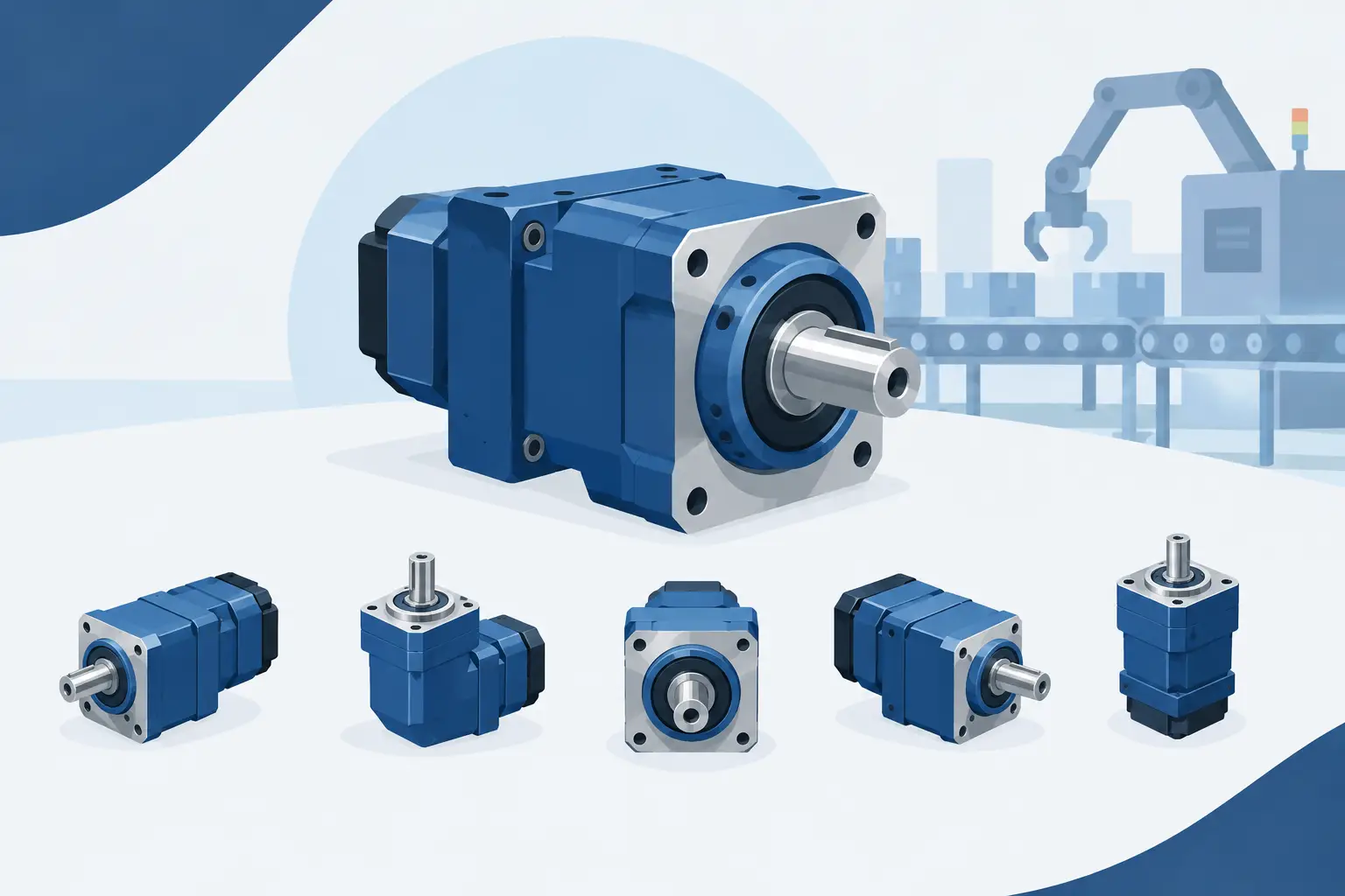
A reducer is only compact if it fits the machine around it. The best compact reducer layouts do more than achieve a high ratio in a small envelope: they control shaft position, bearing loads, housing diameter, assembly access and manufacturability. A nominally small gearbox that forces an oversized housing or awkward motor mount is not a compact solution.
For product developers and machine builders, layout selection should start with the output requirement, not the gear type. Define the required torque, speed, duty cycle, permissible backlash, available envelope and output-axis location. Then choose the mechanism that places the ratio where the machine can use it.
What makes a reducer layout genuinely compact?
Compactness has three dimensions: radial size, axial length and installation volume. A planetary stage is usually excellent radially because several planets share the torque around a central sun gear. A cycloidal reducer can deliver a large ratio in a shallow axial package, but its eccentric motion and output-pin arrangement need careful housing clearance. A parallel-axis train may occupy more plan area, yet can be the most compact answer when the motor must sit beside the driven shaft.
Load path matters just as much as the outside dimensions. High tangential tooth loads need bearing spacing, a stiff carrier or housing, and shafts that do not deflect enough to alter mesh conditions. If these supporting parts are ignored during concept work, the calculated ratio may fit while the real assembly does not.
The practical question is not, “Which reducer is smallest?” It is, “Which layout gives the required output in the smallest buildable assembly?”
Best compact reducer layouts by packaging need
Planetary reducers for coaxial drives
A planetary gearbox is the default compact layout when motor and output shafts must remain on the same centreline. The sun gear drives multiple planet gears, which run inside a ring gear and transmit torque through a carrier. Because torque is divided between planets, the layout can achieve good torque density without a large housing diameter.
Single-stage planetary layouts are useful where a moderate reduction is enough. The exact ratio is governed by the tooth counts of the sun and ring, so ratio choice is not completely free. Tooth-count combinations must also satisfy assembly conditions, particularly where equally spaced planets are required. Forcing an unsuitable tooth combination can produce a mechanism that looks correct in a sketch but cannot be assembled with the intended planet count.
For higher reductions, compound planetary arrangements or multiple stages keep the input and output coaxial. The trade-off is axial length, added bearings and cumulative backlash. A two-stage planetary gearbox is often still shorter than a large-diameter single-stage alternative, but only if the carrier, ring gear and interstage shaft are designed as an assembly rather than separate gear calculations.
Use a planetary layout when concentric motor mounting, high torque density and clean installation geometry take priority. It is less attractive where low-cost manufacture is the main constraint, or where the required ratio demands impractical tooth counts in a single stage.
Cycloidal reducers for high ratios in short packages
Cycloidal layouts are strong candidates where a high reduction ratio and overload tolerance are needed within limited diameter and axial space. An eccentric input moves a cycloidal disc against a fixed ring of pins or rollers. The small tooth-count difference between disc and ring creates the reduction, while output pins collect the slow rotation.
The layout has a useful characteristic: it can achieve ratios that would require several ordinary gear stages in a compact package. With multiple discs phased apart, cyclic forces can be balanced more effectively and torque capacity can increase. This makes cycloidal mechanisms well suited to robot joints, indexing equipment, compact rotary axes and drives that see intermittent shock loads.
The constraint is precision. Eccentricity, pin diameter, disc profile, clearance and output-pin geometry interact directly. Too little clearance risks interference and heat; too much creates lost motion and uneven loading. The output bearing arrangement also deserves early attention, because the reducer may carry significant radial and moment loads depending on the application.
Choose cycloidal when ratio density matters more than simple conventional gear manufacture. It is not automatically the best option for every small drive. A modest ratio with continuous, quiet operation may be better served by a planetary or helical layout.
Parallel-axis and offset layouts for flexible motor placement
A parallel-axis reducer places input and output shafts side by side. It is often dismissed as less compact because the gears sit next to each other rather than concentrically. That misses the packaging advantage: it can reduce total machine depth when the motor can sit alongside the driven shaft, under a guard or within a frame member.
Spur gears provide direct geometry and efficient manufacture. Helical gears can carry higher loads with smoother engagement, but introduce axial thrust that must be absorbed by the bearings and housing. In a compact unit, this is not a minor detail. Bearing selection, shoulder locations and retention features can add more axial length than the helical gear pair saves in face width.
Two or three parallel stages can deliver substantial ratios, especially where the housing can extend laterally. The designer must manage pinion tooth count carefully to avoid undercut and weak root sections. A larger module may improve tooth strength but increases centre distance; a smaller module reduces envelope but raises sensitivity to manufacturing quality and shaft deflection.
This layout works well for conveyors, compact machine axes, tooling mechanisms and retrofits where the output shaft cannot share the motor centreline. It is often the most honest choice when installation geometry, rather than catalogue gearbox shape, drives the design.
Bevel and right-angle reducers for changing direction
A right-angle reducer earns its place when it removes a separate transmission component. Bevel gears, spiral bevel gears or a bevel stage combined with further reduction can turn drive direction through 90 degrees while keeping the motor out of the output axis.
This is valuable in tight enclosures, wheel modules and machines where the motor must be protected behind a structural plate. However, bevel gears impose stricter alignment requirements than a basic spur pair. Mounting distance, shaft position and bearing stiffness influence tooth contact. A compact right-angle housing must resist separating forces without allowing the gear mesh to move under load.
Use a bevel layout because the change in direction improves the whole machine package, not merely because it appears shorter in one view. If no directional change is required, the additional stage and alignment demand may not justify it.
Configure the reducer as an assembly, not a ratio
A productive design workflow moves through four checks: configure, inspect, validate and export. Start by setting the intended ratio, torque path, tooth system, shaft diameters and available housing envelope. Then inspect the actual three-dimensional assembly. Look for carrier clearance, gear overlap, tool access, motor interface conflicts and the space required for bearings, circlips and fasteners.
Validation should include more than centre distance and nominal ratio. Check whether the selected module and tooth counts produce viable teeth, whether planets can be phased and assembled, whether helical thrust has a bearing path, and whether wall thickness remains credible around ring gears and bearing seats. For cycloidal systems, inspect the full eccentric sweep rather than only a static position.
Export geometry only after the mechanism is coherent. Manufacturing files need real solids with mating features, not visual approximations. Shafts need sensible shoulders and fit locations. Housings need bearing bores, retention strategy and assembly split lines. A reducer that cannot be assembled, lubricated or serviced is not finished engineering.
GearSuite is designed around this mechanism-first approach: configure the transmission, inspect its assembly geometry, receive direct engineering feedback, then generate manufacturable solids for CAD handoff. Decisions stay visible.
The best layout is the one that preserves space for the parts engineers are tempted to leave until later: bearings, housing walls, fasteners, lubrication and assembly clearance. Make room for those from the first model, and the reducer will remain compact when it becomes real.